
Subscribe to Our Youtube Channel
Related Manuals for HACH LANGE FP 360 sc


Summary of Contents for HACH LANGE FP 360 sc
- Page 1 DOC023.52.90161 FP 360 sc User Manual 01/2010, Edition 1B © HACH-LANGE GmbH, 2010. All rights reserved. Printed in Germany...
-
Page 3: Table Of Contents
2.1.2 Precautionary labels ........................7 2.2 Product overview ..........................8 2.3 Measuring principle..........................8 2.4 Product components........................... 8 2.4.1 FP 360 sc sensor ........................9 2.5 Function test ............................9 Section 3 Installation ..........................11 3.1 Connect sensor cable ........................11 3.2 Installation options .......................... - Page 4 Table of Contents Section 6 Troubleshooting ........................25 6.1 Error messages ..........................25 6.2 Warnings ............................25 6.3 Replacement parts ..........................25 Section 7 Replacement parts and accessories ................27 7.1 Sensor options ..........................27 7.2 Replacement parts ..........................27 7.3 Accessories ............................27 Section 8 Contact information ......................29 Section 9 Warranty and Liability......................31 Appendix A Modbus register ......................33 Index ...............................35...
-
Page 5: Section 1 Specifications
Section 1 Specifications Specifications are subject to change without notice. Measurement UV fluorescent measurement process for polycyclic aromatic Hydrocarbons (PAH) Measurement method Excitation wavelength: 254 nm Emission (measurement) wavelength: 360 nm 0 to 50 ppb and 0 to 500 ppb in relation to PAH calibration standard, Low measurement range corresponding to 0.1 to 1.5 ppm and 0.1 to 15 ppm of oil calibration standard... -
Page 6: Dimensions
Specifications Environment considerations Sample temperature 1 to 40 °C (34 to 104 °F) –5 to +45 °C (23 to 113 °F) Measurement sensor wetted by at least half from the measuring Ambient temperature medium: –25 to +55 °C (-13 to 131 °F) Sensor distance - wall/ground min. -
Page 7: Section 2 General Information
Section 2 General information 2.1 Safety information Please read this entire manual before unpacking, setting up or operating this equipment. Pay attention to all danger and caution statements. Failure to do so could result in serious injury to the operator or damage to the equipment. Make sure that the protection provided by this equipment is not impaired, do not use or install this equipment in any manner other than that specified in this manual. -
Page 8: Product Overview
Remove the measurement sensor from operation before carrying out any maintenance or installation work. The FP 360 sc sensor is a UV fluorimeter used to continuously measure the concentration of PAH (polycyclic aromatic hydrocarbons) in water. The measurement values can be converted to reflect the total oil content for mineral oils using lab data. -
Page 9: Fp 360 Sc Sensor
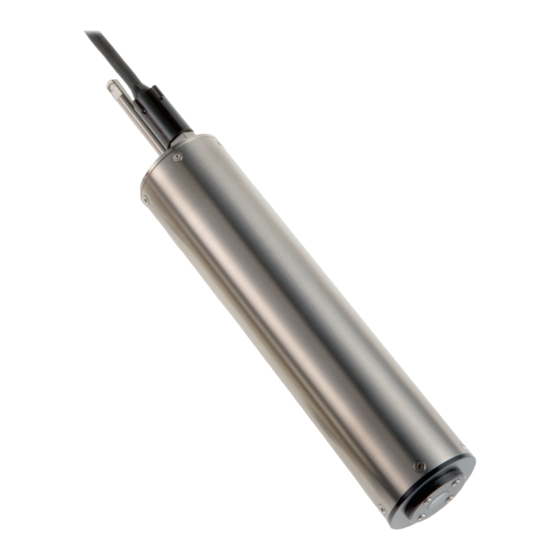
General information 2.4.1 FP 360 sc sensor Figure 2 FP 360 sc sensor FP 360 sc measurement sensor 6 mm fitting for cleaning unit (depending on model) Basic user manual with CD Safety sleeve Measurement window Connector cable Sensor with cleaning unit (depending on model) Shackle 2.5 Function test... - Page 10 General information 3. Cover the sensor measurement window with a sheet of white paper (do not use recycled paper). 4. Vary the distance between the measurement window and the paper. The measurement value on the display will change accordingly. Note: In air, the measurement value displayed is not exactly zero due to reflections on the window surface (refer to section 4.5.3 on page...
-
Page 11: Section 3 Installation
Section 3 Installation D A N G E R Personal injury hazard. Only qualified personnel should conduct the tasks described in this section of the manual. N O T I C E If the sensor is not fully inserted, sun protection is recommended in high ambient temperatures and intense solar radiation to protect against thermal and UV effects. - Page 12 Installation Figure 4 Connect the sensor to the controller Figure 5 Pin configuration Number Description Standard cable, cable color +12 VDC brown Ground black Data (+) blue Data (–) white Screen Screen (gray) Guide...
-
Page 13: Installation Options
Note: Refer to the documentation supplied with the accessories for detailed installation instructions. 3.2.1 Installation with the chain mount kit The FP 360 sc sensor is installed with the chain mount kit in open channels, shafts and tanks. Figure 6 FP 360 sc measurement sensor with chain mount kit 3.2.2 Installation of chain mount kit for sensors with cleaning unit... - Page 14 Installation Figure 7 Install the cleaning unit hose Figure 8 FP 360 sc measurement sensor with cleaning unit and chain mount kit...
-
Page 15: Installation With Flow Cell
Installation 3.2.3 Installation with flow cell The FP 360 sc sensor with flow cell is installed for samples free of solids and particulates and limited sample flows. Figure 9 Installation with flow cell... - Page 16 Installation...
-
Page 17: Section 4 Operation
Section 4 Operation 4.1 User interface and navigation The sensor can be used with sc controllers from sc100. Refer to the controller documentation for keypad description and navigation information. 4.2 Sensor setup When the sensor is connected for the first time, the sensor serial number is displayed as the name of the sensor. -
Page 18: Menu Structure
Operation 4.4 Menu structure 4.4.1 SENSOR STATUS SELECT SENSOR (if there is more than one sensor) ERROR LIST Possible error messages: SENSOR ERROR Possible warning messages: TEST/MAINT, BULB CHANGE, LAST CONFIGUR, TARGET WARNING LIST VALUE Note: Refer to Section 6 on page 25 for a list of all possible error and warning messages together with a description of all necessary countermeasures to be taken. - Page 19 Operation 4.4.2 SENSOR SETUP (Continued) SELECT SENSOR (if there is more than one sensor) CONFIGURE Name can include up to 16 characters, EDIT NAME DEFAULT CONFIG: sensor serial number PAH: Measurement value related to PAH calibration standard SET PARAMETER OIL: Measurement value related to oil calibration standard DEFAULT CONFIG: PAH ppb, ppm, μg/L, mg/L,...
-
Page 20: Calibration
Operation 4.5 Calibration 4.5.1 Factory calibration The calibration curve zero point and slope are preset. Retrospective calibration of these basic settings is generally not required outside of the inspection intervals. Do regular zero point checks to make sure that impurities or faults are being detected (refer to section 4.5.3 on page 21). -
Page 21: Multi-Point Calibration
Operation 6. Enter the factor as the slope (refer to section 4.5.4.1 on page 21). Example for engine oil Example for naphthalene Lab value: 4.0 ppm oil Lab value: 420 ppb PAH Measurement value shown : 2.4 ppm oil Measurement value shown : 120 ppb PAH... -
Page 22: Adjust The Zero Point (Offset)
Operation 4.5.4.2 Adjust the zero point (OFFSET) 1. Open the MAIN MENU. 2. Select SENSOR SETUP and confirm. 3. Select the corresponding sensor and confirm. 4. Select CALIBRATE and confirm. 5. Select CONFIGURE and confirm. 6. Press OFFSET and confirm. 7. -
Page 23: Section 5 Maintenance
Section 5 Maintenance The inside of the sensor is maintenance-free. The cleanliness of the measurement window in the sensor head has an impact on the accuracy of measurements. Check the measurement window at regular intervals to make sure it is clean. The required frequency of these checks is dependent on the measuring medium. -
Page 24: Cleaning The Measurement Windows
Maintenance 5.3 Cleaning the measurement windows C A U T I O N Cleaning agents can be hazardous to health. Wear protective equipment and avoid direct contact with cleaning fluids. N O T I C E Other cleaning agents can damage the material. Damage caused by cleaning carried out incorrectly is not covered by the warranty. -
Page 25: Section 6 Troubleshooting
Section 6 Troubleshooting 6.1 Error messages Possible sensor errors displayed by the sc controller. Displayed errors Definition Resolution SENSOR ERROR Electronic defect Call manufacturer customer service 6.2 Warnings Possible sensor warning messages displayed by the sc controller. Displayed warnings Definition Resolution DIAG/TEST Counter expired... - Page 26 Troubleshooting...
-
Page 27: Section 7 Replacement Parts And Accessories
V4A chain mount kit LZX914.99.11110 HOAB compressed air cleaning system, 230 V 6860103.99.0001 HOAB compressed air cleaning system, 115 V, HACH Lange version 6860003.99.0001 Hose for air and measuring medium 5 m, 6/4 mm external/internal diameter LZY619 Hose for air and measuring medium 10 m, 6/4 mm external/internal diameter... - Page 28 Replacement parts and accessories 7.3 Accessories (table continued) Description Cat. no. Hose for measuring medium 5 m, 8/6 mm external/internal diameter LZY672 Hose for measuring medium 10 m, 8/6 mm external/internal diameter LZY673...
-
Page 29: Section 8 Contact Information
Fax (204) 694-5134 80539-0389 U.S.A. www.hach.com canada@hach.com Tel +001 (970) 669-3050 Fax +001 (970) 669-2932 intl@hach.com HACH LANGE GMBH HACH LANGE LTD HACH LANGE LTD HACH LANGE GMBH Willstätterstraße 11 Pacific Way Unit 1, Chestnut Road Hütteldorferstr. 299/Top 6... - Page 30 Contact information HACH LANGE D.O.O. ΗΑCH LANGE E.Π.Ε. HACH LANGE E.P.E. HACH LANGE D.O.O. Fajfarjeva 15 Αυλίδος 27 27, Avlidos str Ivana Severa bb SI-1230 Domžale GR-115 27 Αθήνα GR-115 27 Athens 42 000 Varaždin Tel. +386 (0)59 051 000...
-
Page 31: Section 9 Warranty And Liability
Section 9 Warranty and Liability The manufacturer warrants that the product supplied is free of material and manufacturing defects and undertakes the obligation to repair or replace any defective parts at zero cost. The warranty runs for 24 months. If a maintenance contract is taken out within 6 months of purchase, the warranty period is extended to 60 months. - Page 32 Warranty and Liability...
-
Page 33: Appendix A Modbus Register
Appendix A Modbus register Table 1 Sensor Modbus registers Register# Data type Length Description 40001 Unsigned integer Reserved 40002 Float Measurement value as PAH, unit PPB 40004 Float Measurement value as PAH, unit PPM 40006 Float Measurement value as OIL, unit PPB 40008 Float Measurement value as OIL, unit PPM... - Page 34 Modbus register...
-
Page 35: Index
Index Measurement accuracy ..........5 Measuring method ............. 5 Areas of application ........... 8 Measuring principle ............ 8 Measuring range ............5 Modbus register ............33 Calibration ..............5 Chain mount kit ............13 Precautionary labels ........... 7 Pressure range ............5 Data logger .............. - Page 36 Index...
Need help?
Do you have a question about the FP 360 sc and is the answer not in the manual?
Questions and answers