Table of Contents

Subscribe to Our Youtube Channel
Related Manuals for Metrohm 793 IC


Summary of Contents for Metrohm 793 IC
- Page 1 793 IC Sample Prep Module IC Sample Prep Module Metrohm POWER REMOTE REMOTE ACTUATOR PUMP STEP Instructions for Use CH-9101 Herisau/Schweiz E-Mail info@metrohm.com 8.793.1003 Internet www.metrohm.com...
- Page 2 CH-9101 Herisau/Switzerland E-Mail info@metrohm.com Internet www.metrohm.com 793 IC Sample Prep Module Instructions for Use 8.793.1003 06.2001 / up...
-
Page 3: Table Of Contents
Exchanging the pump tubing ............. 31 4.2.5 Regeneration of the cation exchange material ......32 4.2.6 Cleaning the SP Module A............33 4.2.7 Exchanging the cation exchange material ......... 35 4.2.8 Braking range adjustment ............36 793 IC Sample Prep Module/ 8.793.1003 Instructions for Use... - Page 4 Installing pump tubings ...................13 Fig. 8: Connection 793 IC Sample Prep Module - Modular IC System for cation elimination............18 Fig. 9: Assembling the actuator..................34 Fig. 10: Adjusting the braking range ................37 793 IC Sample Prep Module/ 8.793.1003 Instructions for Use...
-
Page 5: Introduction
Cation Separation (e.g. exchange of heavy metals by H ). Of course the 793 IC Sample Prep Module can also be combined with all other HPLC components currently on the market. Although in principle the techniques of cation exchange by the 793 IC... -
Page 6: Parts And Controls
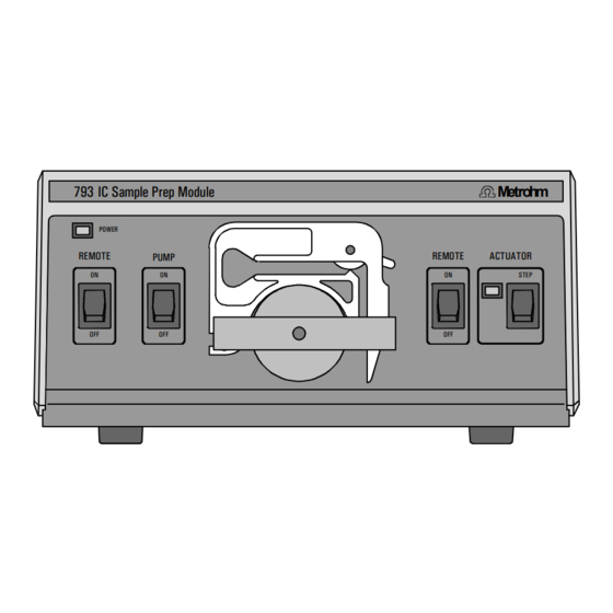
PUMP REMOTE ACTUATOR STEP 9 9 9 9 Fig. 1: Front of the 793 IC Sample Prep Module 1 1 1 1 Power on lamp 7 7 7 7 SP Module A position display Lights up when instrument is switched Is lit up when the actuator is "in position"... -
Page 7: Fig. 2: Rear Of The 793 Ic Sample Prep Module
For continued protection replace only Made by Metrohm Herisau Switzerland with the same type and rating of fuse Fig. 2: Rear of the 793 IC Sample Prep Module Mains switch Connection for SP Module A For switching the instrument on/off:... -
Page 8: Information About The Instructions For Use
Information about the Instructions for Use Please read through these Instructions for Use carefully before you put the 793 IC Sample Prep Module into operation. The Instructions for Use contain information and warnings to which the user must pay attention in order to assure safe operation of the instruments. -
Page 9: Notation And Pictograms
Caution This symbol marks important information. First read the associ- ated directions before you con- tinue. Comment This symbol marks additional information and tips. 793 IC Sample Prep Module/ 8.793.1003 Instructions for Use... -
Page 10: Safety Notes
1.4.1 Electrical safety While electrical safety in the handling of the 793 IC Sample Prep Mod- ule is assured in the context of the specifications IEC 1010-1 (protection class I, degree of protection IP20), the following points should be no-... -
Page 11: Installation
2.1.4 Arrangement of the instruments The best position for the 793 IC Sample Prep Module is beside the Mo- dular IC System (e.g. 733 IC Separation Center). The 793 IC Sample Prep Module should always be placed at the... -
Page 12: Mains Connection
2.2.1 Setting the mains voltage Before switching on the 793 IC Sample Preparation Module for the first time, check that the mains voltage set on the instrument (see Fig. 2) matches the local mains voltage. If this is not the case, you must reset... -
Page 13: Fuses
Sample Prep Module (see Fig. 4). 2.2.4 Switching the instrument on/off The 793 IC Sample Prep Module is switched on and off using mains switch 13 13. When the instrument is switched on lamp 1 1 1 1 lights up. -
Page 14: Connection To A Modular Ic System For Neutralization
2.3.1 Electrical connection The 793 IC Sample Prep Module is connected to an IC system consist- ing of 732 IC Detector, 733 IC Separation Center (two injectors), 709 IC Pump, 752 IC Pump Unit, 753 IC Suppressor Module and 762 IC Inter- face as shown in Fig. -
Page 15: Connection Of The Sp Module A
Center (two injectors). The 1.793.0110 SP Module A must first be inserted in the 733 IC Sepa- ration Center and connected to the 793 IC Sample Prep Module. Addi- tionally, the suppressor block of the 753 Suppressor Module is inserted and connected, which is described in detail in the corresponding 8.753.1001 Instructions for Use. -
Page 16: Fig. 6: Connections At Sp Module A
Inlet capillary for acid Regenerant Sample out Outlet capillary for acid Outlet capillary for H Waste Inlet capillary for H Outlet capillary for sample Waste Fig. 6: Connections at SP Module A 793 IC Sample Prep Module/ 8.793.1003 Instructions for Use... -
Page 17: Fig. 7: Installing Pump Tubings
Snap-action lever Pump tubing (6.1826.010) SP Module A inlet capillary Stopper (white-white) for HClO SP Module A inlet capillary PEEK coupling (6.2744.110) for H PTFE tubing (6.1803.020) PEEK filter unit (6.2821.100) 793 IC Sample Prep Module/ 8.793.1003 Instructions for Use... - Page 18 22 (see Fig. 6) through one of the rear panel ope- nings 41 41 or 43 43 of the IC Separation Center 733. Lead outlet capillary 27 27 to a sufficiently large waste container and fix in place. 793 IC Sample Prep Module/ 8.793.1003 Instructions for Use...
- Page 19 Startup of 793 IC Sample Prep Module Set switch <REMOTE> 2 2 2 2 to "OFF". Switch on 793 IC Sample Prep Module with mains switch 13 and set switch <PUMP> 3 3 3 3 to "ON". Adjust the contact pressure for both tubing cartridges: press contact pressure lever 5 5 5 5 upwards until the solutions just start to be drawn in.
-
Page 20: Settings In The "Ic Net 2.1" Program
2 Installation 2.3.3 Settings in the «IC Net 2.1» program During configuration of the 793 IC Sample Prep Module and 753 Sup- pressor Module the IC Net assistant “New system wizard” requires the definition of “Event lines” for the SP Module A and suppressor, respec- tively. - Page 21 Neutralization.smt Probe 3 Neutralization.smt Probe 4 Neutralization.smt Probe 5 End-Neutralization.smt dummy This example describes the processing of a queue with five samples. The column 'Chrom. No.' is just given for information. 793 IC Sample Prep Module/ 8.793.1003 Instructions for Use...
-
Page 22: Connection To A Modular Ic System For Cation Elimination
Connection to a Modular IC System for Cation Elimination A second application for the 793 IC Sample Prep Module is cation elimination before chromatographic separation of the sample on the column (e.g. precolumn elimination of heavy metals). In this section a system for determination of anions with chemical suppression is described. -
Page 23: Connection Of The Sp Module A
Separation Center (one injector + MSM). The 1.793.0110 SP Module A must first be inserted in the 733 IC Separation Center and connected to the 793 IC Sample Prep Module. The connection of all parts should be done as described by the... - Page 24 41 41 41 or 43 43 43 43 of the 733 IC Separation Center. Lead outlet capillary 26 26 26 26 to a sufficiently large waste container and fix in place. 793 IC Sample Prep Module/ 8.793.1003 Instructions for Use...
- Page 25 Startup of 793 IC Sample Prep Module Set switch <REMOTE> 2 2 2 2 to "OFF". Switch on 793 IC Sample Prep Module with mains switch 13 and set switch <PUMP> 3 3 3 3 to "ON". Adjust the contact pressure for both tubing cartridges: press contact pressure lever 5 5 5 5 upwards until the solutions just start to be drawn in.
-
Page 26: Settings In The "Ic Net 2.1" Program
733 IC Separation Center parameter “Auto Step” must be set to “fill”. The peristaltic pumps of the 752 IC Pump Unit and 793 IC Sample Prep Module are started when the IC system is activated (measuring baseline). For this , the option ’Start pump with startup hardware... -
Page 27: Operation
The SP Module A must never be switched in the dry state as there is a danger of blocking. No recycling The recycling process (returning the eluent to the storage vessel) must not be carried out when the SP Module A is in operation. 793 IC Sample Prep Module/ 8.793.1003 Instructions for Use... -
Page 28: Manual Operation
(mains connection, attaching the pump tubing, connection to the IC system). Switch instrument on/off The 793 IC Sample Prep Module is switched on and off using mains switch 13 13 on the rear of the instrument (see Fig. 2): Instrument switched on... -
Page 29: Operation Via Ic Detector 732
Automatic pump switch-on when the 732 IC Detec- tor is switched on In order to start up the pump drive of the 793 IC Sample Prep Module automatically when the 732 IC Detector is switched on alterations must be made to the basic settings (Setup, see section 4.4.1 of 732/733 Manual). - Page 30 ✴ ✴ ✴ ✴ ✴ ✴ ✴ ✴ ✴ ✴ ✴ ✴ ✴ ✴ ✴ ✴ ✴ ✴ ✴ ✴ ✴ ✴ ✴ ✴ ✴ ✴ ✴ ✴ or with autosamplers). 793 IC Sample Prep Module/ 8.793.1003 Instructions for Use...
- Page 31 ✴ ✴✴✴✴✴✴ SP Module A position display The position display 7 7 7 7 of the 793 IC Sample Prep Module beside ACTUATOR switch 8 8 8 8 shows whether the SP Module A is in the right position: STEP...
-
Page 32: Malfunctions - Maintenance
Air bubbles in pump Suction tubing is not immersed Immerse the suction tubing fully in the circuit regenerating or rinsing solution. Leaking tubing connectors Tighten or replace the leaking tubing connectors. 793 IC Sample Prep Module/ 8.793.1003 Instructions for Use... - Page 33 If display lamp 7 7 7 7 does not light up each time the position is changed then the braking range must be readjusted (see below). Actuator dirty Clean actuator (see section 4.2.6). Mechanical fault in Actuator Exchange actuator (see section 4.2.7). 793 IC Sample Prep Module/ 8.793.1003 Instructions for Use...
-
Page 34: Maintenance And Servicing
1.4.1. 4.2.2 Maintenance by Metrohm service Maintenance of the 793 IC Sample Prep Module is best done as part of an annual service performed by specialists from the Metrohm company. Due to caustic and corrosive chemicals which are processed by this device, it may be necessary to shorten the interval between servicing. -
Page 35: Exchanging The Pump Tubing
Release tubing cartridge 4 4 4 4 from holding clamp 9 9 9 9 by pressing down snap-action lever 10 10 and remove from mounting pin 12 on the 793 IC Sample Prep Module (see Fig. 1). Remove old pump tubing. Insert new pump tubing Insert the new pump tubing 33 33 (6.1826.010) in the tubing... -
Page 36: Regeneration Of The Cation Exchange Material
Connect SP Module A to IC system Reconnect SP Module A to IC system. If there are still prob- lems with the capacity then the actuator rotor must be ex- changed (see section 4.2.6). 793 IC Sample Prep Module/ 8.793.1003 Instructions for Use... -
Page 37: Cleaning The Sp Module A
4 mm inside the holder. If this is not the case then the rotor must be brought into the correct position from below with the aid of a sharp object (e.g. screwdriver). 793 IC Sample Prep Module/ 8.793.1003 Instructions for Use... -
Page 38: Fig. 9: Assembling The Actuator
Reconnect the SP Module A to the IC system (see section 2.3.2 and section 2.4.2). Before switching the actuator to the next position for the first time rinse all 3 actuator units with solution for 5 min. 793 IC Sample Prep Module/ 8.793.1003 Instructions for Use... -
Page 39: Exchanging The Cation Exchange Material
(see Fig. 9): Disconnect SP Module A from IC system Disconnect all input and output leads of the SP Module A from IC system and the pump of the 793 IC Sample Prep Module. Dismantle actuator... -
Page 40: Braking Range Adjustment
4.2.8 and readjust if necessary. 4.2.8 Braking range adjustment It may be necessary to readjust the braking range of the 793 IC Sample Prep Module in the following cases (see also section 4.1): Actuator switches to next position but display lamp 7 7 7 7 no longer lights up When the actuator is exchanged (see section 4.2.7) -
Page 41: Fig. 10: Adjusting The Braking Range
Wait at least 10 s each time before operating key 8 8 8 8 <STEP>. unzulässig zulässig optimal zulässig unzulässig not acceptable acceptable optimum acceptable not acceptable Fig. 10: Adjusting the braking range 793 IC Sample Prep Module/ 8.793.1003 Instructions for Use... -
Page 42: Appendix
* A precondition for triggering a step is that the current flows for at least 10 ms. In order that a new step can be triggered no current must flow for at least 10 ms before. 793 IC Sample Prep Module/ 8.793.1003 Instructions for Use... - Page 43 Polyurethane rigid foam (PUR) with fire protection for fire class UL94VO, CFC-free Material of base Steel, enamelled Dimensions Width 260 mm Height 129 mm Depth 366 mm Weight 6.0 kg (incl. accessories) 793 IC Sample Prep Module/ 8.793.1003 Instructions for Use...
-
Page 44: Standard Equipment
Connection between 6.2744.010 PEEK compression fitting and 6.1826.0X0 pump tubing (also supplied together with 733.0030 IC Separation Center); Set of 4 pcs 6.2744.040 PEEK coupling ") For the connection of capillaries ( 793 IC Sample Prep Module/ 8.793.1003 Instructions for Use... -
Page 45: Optional Accessories
RS232 connection 762 IC Interface – 1 external device (709, 732, 766, etc.) 6.2143.210 Cable Connection 793 IC Sample Prep Module – 732 IC Detector 6.2835.000 Actuator rotor 6.2835.010 Connection piece to actuator rotor 793 IC Sample Prep Module/ 8.793.1003 Instructions for Use... -
Page 46: Warranty And Conformity
Lack of an official damage report releases Metrohm from any liability to pay compensation. If any instruments and parts have to be returned, the original packaging should be used if at all possible. -
Page 47: Eu Declaration Of Conformity
5.4 Warranty and conformity 5.4.2 EU Declaration of conformity EU Declaration of Conformity The METROHM AG company, Herisau, Switzerland hereby certifies, that the in- strument: 793 IC Sample Prep Module meets the requirements of EC Directives 89/336/EWG and 73/23/EWG. Source of the specifications:... -
Page 48: Certificate Of Conformity And System Validation
International Certification Body (CB/IEC). The technical specifications are documented in the instruction manual. Metrohm Ltd. is holder of the SQS-certificate of the quality system ISO 9001 for quality assurance in design/development, production, installation and servicing. Herisau, October 30, 2000 Dr. -
Page 49: Index
Opening the IC Sample Prep Module..6 Figure..........2 Figure ..........2,13 Operation..........23 Install tubing cartridges ..13,20,31 Install tubing cartridges ....13,20 Operation via 732 IC Detector....25 Housing..........39 Control unit..........1 793 IC Sample Prep Module / 8.793.1003 Instructions for Use... - Page 50 Rinsing solution ....... 14,21 Installation .......13,20,31 Rotate SP Module A ....16,22,24,26 Two-channel system (733)....10 Rotate SP Module A at an event ..27 Rotate SP Module A in a program ..26 793 IC Sample Prep Module / 8.793.1003 Instructions for Use...
Need help?
Do you have a question about the 793 IC and is the answer not in the manual?
Questions and answers