Subscribe to Our Youtube Channel
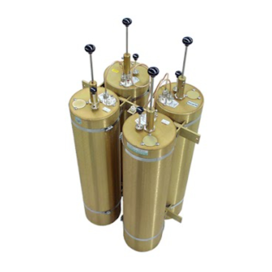
Summary of Contents for TX RX Systems 28-13-01F
- Page 1 Instruction Manual Vari-Notch Duplexers (6" Cavities) Copyright © 1997 TX RX Systems, Inc. SYSTEMS INC. 8625 Industrial Parkway Angola, NY 14006-9696 (716) 549-4700 24-hr Fax (716) 549-4772 A Member of Bird Technologies Group...
- Page 2 Vari-Notch Duplexers (6" Cavities) Copyright © 1997 TX RX Systems, Inc. First Printing : September 1997 Version Number Version Date 09/19/97 84YCB TX RX SYSTEMS INC. 8625 INDUSTRIAL PARKWAY, ANGOLA, NY 14006 TELEPHONE 716-549-4700 716-549-4772 (24 HRS.) A MEMBER OF BIRD TECHNOLOGIES GROUP...
-
Page 3: Warranty
TX RX SYSTEMS INC. reserves the right to replace with merchandise of equal per- formance although not identical in every way to that originally sold. TX RX SYSTEMS INC. is not liable for damage caused by lightning or other natural disasters. No product will be accepted for re- pair or replacement without our prior written approval. - Page 4 28-36-11E/G 132-150 28-37-02A/G 144-174 28-37-11E/G 144-174 28-37-08G 144-174 0.24 28-65-01A 406-430 28-65-05A/G 406-430 28-70-01A 450-470 28-70-07A/G 450-470 28-69-01A 470-512 28-69-04A 470-512 Table 1: Vari-Notch Duplexer electrical specifications (for 6.625" diameter cavities). TX RX Systems Inc. Manual 7-9177-1 09/19/97 Page 1...
-
Page 5: Installation
Check for loose or corroded connectors on TX RX Systems Inc. It is also important to observe TX RX Systems Inc. Manual 7-9177-1 09/19/97... - Page 6 For instance, the specification for response. When reconnecting the assembly, it is model 28-13-01F is 1.5 dB, this means both the high and low frequency channels will each have a TX RX Systems Inc.
- Page 7 5. Female union (UG29-N or UG914-BNC). KHz/DIV KHz RES 6. Return Loss Bridge (Eagle model# RLB150N3A). 7. Insulated tuning tool (TX RX Systems Inc. part# 95-00-01). Tuning Procedure Tuning of the filter requires adjustment of the dB ATT passband and the rejection notch . The passband...
- Page 8 MODE - live rod hard to move in or out. This occurs because FILTER - none TX RX Systems Inc. uses construction techniques SETUP - 50 ohm/dBm/gen1. borrowed from microwave technology that provide 5. The flat line across the screen is the return loss curve.
- Page 9 The notch is adjusted by turning the variable ca- pacitor. Because of the filters sensitivity to tool contact, an insulated tuning tool must be used to Figure 5: Checking the rejection notch. make the adjustment. TX RX Systems Inc. Manual 7-9177-1 09/19/97 Page 6...
- Page 10 Notch Notch Filter Filter Load Low Frequency Pass Channel Reject the High Frequency Channel RLB - 150 BRIDGE (RLB) Figure 6: Equipment setup for fine tuning the passband of each channel. TX RX Systems Inc. Manual 7-9177-1 09/19/97 Page 7...
- Page 11 GENERATE INPUT OUTPUT Vari- Vari- Notch Notch Filter Filter Low Frequency Pass Channel Reject the High Frequency Channel Figure 7: Equipment setup for fine tuning the rejection notch of each channel. TX RX Systems Inc. Manual 7-9177-1 09/19/97 Page 8...
- Page 12 (usually indicated by the same number of Tx and Rx filter sections) just reverse the equipment labels and operate. Generally, no damage will be done to the duplexer when operated in reverse for a short time period. If other adverse symptoms appear, con- tact the factory. TX RX Systems Inc. Manual 7-9177-1 09/19/97...
- Page 13 Duplexer isolation should be measured first per instruction manual to verify rated specifications are present. If more duplex iso- lation is required, contact TX RX SYSTEMS for recommended filtering. Consult the factory. Bandpass filter tests can be made to confirm this. In extreme cases, adjustments to the transmitter ma y be required.
- Page 14 INSERTION LOSS (dB) OUTPUT POWER (WATTS) FOR LOWER POWER LEVELS, DIVIDE BOTH SCALES BY 10 (5 TO 50 WATTS) TX RX Systems Inc. Manual 7-9177-1 09/19/97 Page 11...
- Page 15 1.15:1 1.2:1 1.25:1 1.3:1 1.4:1 1.5:1 1.6:1 1.8:1 2.0:1 2.5:1 3.0:1 10 8.0 6.0 1.0 0.8 0.6 REFLECTED POWER (WATTS) FOR OTHER POWER LEVELS, MULTIPLY BOTH SCALES BY THE SAME MULTIPLIER TX RX Systems Inc. Manual 7-9177-1 09/19/97 Page 12...

Need help?
Do you have a question about the 28-13-01F and is the answer not in the manual?
Questions and answers