Table of Contents
Advertisement
Quick Links
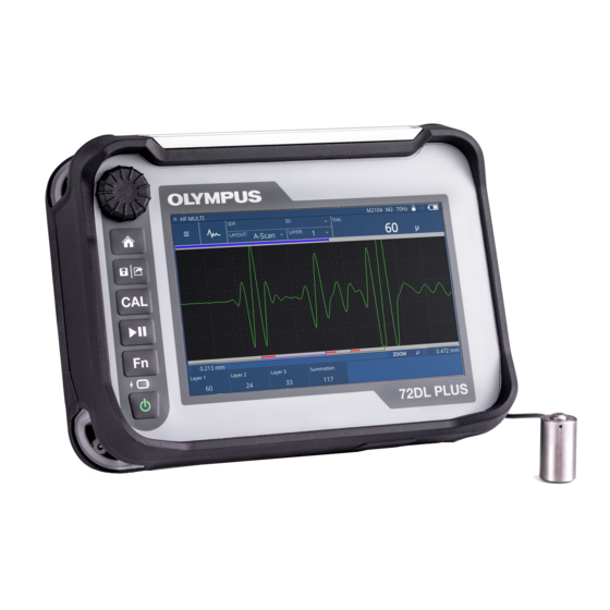
72DL PLUS
Precision Thickness Gauge
User's Manual
This instruction manual contains essential information on how to use this Olympus product safely and effectively.
Before using this product, thoroughly review this instruction manual. Use the product as instructed.
Keep this instruction manual in a safe, accessible location.
10-014357-01EN — Rev. 2
January 2022
Advertisement
Chapters
Table of Contents
Troubleshooting

Related Manuals for Olympus 72DL PLUS


Summary of Contents for Olympus 72DL PLUS
- Page 1 10-014357-01EN — Rev. 2 January 2022 This instruction manual contains essential information on how to use this Olympus product safely and effectively. Before using this product, thoroughly review this instruction manual. Use the product as instructed. Keep this instruction manual in a safe, accessible location.
- Page 2 Olympus Scientific Solutions Americas, 48 Woerd Avenue, Waltham, MA 02453, USA Copyright © 2022 by Olympus. All rights reserved. No part of this publication may be reproduced, translated, or distributed without the express written permission of Olympus. This document was prepared with particular attention to usage to ensure the accuracy of the information contained therein, and corresponds to the version of the product manufactured prior to the date appearing on the title page.
-
Page 3: Table Of Contents
10-014357-01EN, Rev. 2, January 2022 Table of Contents Labels and Symbols ................... 1 Important Information — Please Read Before Use ........5 Intended Use .......................... 5 Instruction Manual ........................ 5 Instrument Compatibility ..................... 6 Repair and Modification ....................... 6 Safety Symbols ........................7 Safety Signal Words ...................... - Page 4 10-014357-01EN, Rev. 2, January 2022 Unpacking the Instrument ..................19 Case Contents ......................19 72DL PLUS Components ..................20 2. Overview ...................... 23 External Connectors ....................23 2.1.1 LEMO Transducer Connectors ..............24 2.1.2 BNC Connector ....................24 2.1.3 19-Pin Connector .................... 25 2.1.4...
- Page 5 10-014357-01EN, Rev. 2, January 2022 Appendix: Specifications ................45 List of Figures ....................51 List of Tables ..................... 53 Table of Contents...
- Page 6 10-014357-01EN, Rev. 2, January 2022 Table of Contents...
-
Page 7: Labels And Symbols
10-014357-01EN, Rev. 2, January 2022 Labels and Symbols A safety-related label and symbols are attached to the 72DL PLUS precision thickness gauge at the location shown in Figure i-1 on page 1. If the label or symbols are missing or illegible, please contact Olympus. -
Page 8: Table 1 Content Of The Rating Label
The EFUP for the 72DL PLUS has been determined to be 15 years. Note: The Environment-Friendly Use Period (EFUP) is not meant to be interpreted as the period assuring functionality and product performance. - Page 9 10-014357-01EN, Rev. 2, January 2022 Table 1 Content of the rating label (continued) The WEEE symbol indicates that the product must not be disposed of as unsorted municipal waste, but should be collected separately. The DC connector polarity symbol. CAUTION To avoid the risk of electric shock, do not touch the inner conductor of the BNC or LEMO connectors.
- Page 10 10-014357-01EN, Rev. 2, January 2022 Labels and Symbols...
-
Page 11: Important Information - Please Read Before Use
WARNING Do not use the 72DL PLUS for any purpose other than its intended use. It must never be used to inspect or examine human or animal body parts. -
Page 12: Instrument Compatibility
Instrument Compatibility The 72DL PLUS thickness gauge is primarily a self-contained unit. However, it does have a series of I/O ports that can be used to connect compatible peripherals and connect it to a PC. The gauge derives its required DC input power from the 72DL PLUS AC charger/adapter or battery pack. -
Page 13: Safety Symbols
10-014357-01EN, Rev. 2, January 2022 Safety Symbols The following safety symbols might appear on the instrument and in the instruction manual: General warning symbol This symbol is used to alert the user to potential hazards. All safety messages that follow this symbol shall be obeyed to avoid possible harm or material damage. Shock hazard caution symbol This symbol is used to alert the user to potential electric shock hazards. -
Page 14: Note Signal Words
10-014357-01EN, Rev. 2, January 2022 CAUTION The CAUTION signal word indicates a potentially hazardous situation. It calls attention to a procedure, practice, or the like that if not correctly performed or adhered to may result in minor or moderate personal injury, material damage, particularly to the product, destruction of part or all of the product, or loss of data. -
Page 15: Warnings
Otherwise, a malfunction or electric shock may result. CAUTION If an unauthorized power supply cord is used to power the instrument or charge the batteries, Olympus cannot guarantee the electrical safety of the equipment. Important Information — Please Read Before Use... -
Page 16: Battery Precautions
Do not expose a battery to moisture or rain; doing so could cause an electric shock. • Only use the 72DL PLUS unit or an external charger approved by Olympus to charge the batteries. • Only use batteries supplied by Olympus. -
Page 17: Equipment Disposal
10-014357-01EN, Rev. 2, January 2022 Equipment Disposal Before disposing of 72DL PLUS gauge, check your local laws, rules, and regulations, and follow them accordingly. CE (European Community) This device complies with the requirements of directive 2014/30/EU concerning electromagnetic compatibility, directive 2014/35/EU concerning low voltage, and directive 2015/863 which amends 2011/65/EU concerning restriction of hazardous substances (RoHS). -
Page 18: China Rohs
The EFUP for the 72DL PLUS has been determined to be 15 years. Note: The Environment-Friendly Use Period (EFUP) is not meant to be interpreted as the period assuring functionality and product performance. -
Page 19: Korea Communications Commission (Kcc)
(that is, in strict accordance with the manufacturer’s instructions), may cause interference. The 72DL PLUS gauge has been tested and found to comply with the limits for an industrial device in accordance with the specifications of the EMC directive. -
Page 20: Fcc (Usa) Compliance
FCC Supplier’s Declaration of Conformity Hereby declares that the product, Product name: 72DL PLUS precision thickness gauge Model: 72DL PLUS Conforms to the following specifications: FCC Part 15, Subpart B, Section 15.107 and Section 15.109. -
Page 21: Ices-001 (Canada) Compliance
Retain packing materials, waybills, and other shipping documentation needed in order to file a damage claim. After notifying the carrier, contact Olympus for assistance with the damage claim and equipment replacement, if necessary. -
Page 22: Technical Support
Technical Support Olympus is firmly committed to providing the highest level of customer service and product support. If you experience any difficulties when using our product, or if it fails to operate as described in the documentation, first consult the user’s manual, and then, if you are still in need of assistance, contact our After-Sales Service. -
Page 23: Introduction
480 pixels with transflective technology and a wide viewing angle for high visibility. The touch screen can simultaneously display the measurement of up to 6 layers. The 72DL PLUS gauge uses a single element transducer for a variety of applications. Olympus offers a standard frequency option, a high-frequency option, and a multilayer software option to solve diverse applications based on a wide range of material thicknesses. - Page 24 10-014357-01EN, Rev. 2, January 2022 Introduction...
-
Page 25: Package Contents
10-014357-01EN, Rev. 2, January 2022 1. Package Contents A complete 72DL PLUS package contains a precision thickness gauge and several key accessories. Unpacking the Instrument The 72DL PLUS precision thickness gauge and accessories are shipped in an industrial transport case. -
Page 26: 72Dl Plus Components
The AC charger/adapter power cord varies by outlet configuration. The exact part number for each power cord also varies by outlet configuration. 72DL PLUS Components Table 3 on page 21 lists the 72DL PLUS precision thickness gauge components. Chapter 1... -
Page 27: Table 3 72Dl Plus Precision Thickness Gauge Components
10-014357-01EN, Rev. 2, January 2022 Table 3 72DL PLUS precision thickness gauge components Component key 72DL PLUS—All models 72DL PLUS (front) Adjustment knob User interface display ① Home key ③ Save/Send key ④ Calibration key ⑤ Play/Pause key ⑥ Function key ⑦... - Page 28 10-014357-01EN, Rev. 2, January 2022 Table 3 72DL PLUS precision thickness gauge components (continued) Component key 72DL PLUS—All models 72DL PLUS (right side) 14 USB A connector ⑭ ⑮ ⑯ ⑰ 15 USB Mini-B connector 16 USB A connector 17 Micro HDMI connector...
-
Page 29: Overview
This chapter describes the location of the controls, connectors, and attachment points on the 72DL PLUS gauge. External Connectors The external connectors are located at the top of the 72DL PLUS gauge (Figure 2-1 on page 23). DC power connector... -
Page 30: Lemo Transducer Connectors
10-014357-01EN, Rev. 2, January 2022 2.1.1 LEMO Transducer Connectors The 72DL PLUS gauge is supplied with sealed LEMO 00 transducer connectors (Figure 2-2 on page 24). A center pin automatically identifies the connected transducer when certain Olympus corrosion dual element transducers are used. -
Page 31: 19-Pin Connector
Figure 2-4 19-pin connector 2.1.4 DC Power Connector The AC charger/adapter connects to the DC power connector of 72DL PLUS gauge to power the instrument and charge the battery (Figure 2-5 on page 25). Figure 2-5 DC power connector Overview... -
Page 32: Battery Compartment
10-014357-01EN, Rev. 2, January 2022 Battery Compartment The battery compartment cover is located on the back of the 72DL PLUS gauge (Figure 2-6 on page 26). Battery compartment cover Figure 2-6 Battery compartment cover—closed Two thumb screws open the battery compartment cover and secure the door when it is closed (Figure 2-7 on page 27). -
Page 33: Data Port
10-014357-01EN, Rev. 2, January 2022 Figure 2-7 Cover thumb screw Data Port The data port contains the 72DL PLUS digital I/O connectors (Figure 2-8 on page 27). USB A connector USB A connector Micro HDMI connector USB Mini-B connector Figure 2-8 Data port connectors... -
Page 34: Usb A Connectors
10-014357-01EN, Rev. 2, January 2022 2.3.1 USB A Connectors Two USB A connectors are used to connect 72DL PLUS gauge to a USB storage device. The USB A connectors must be used with the Olympus USB drive or equivalent to be CE compliant. -
Page 35: Chest Harness
Bottom Bottom mount mount point point Figure 2-9 72DL PLUS mounting points 2.3.5 Chest Harness The chest harness connects to the top and bottom mounting points of the 72DL PLUS gauge (Figure 2-10 on page 30). Overview... -
Page 36: Shoulder Strap
10-014357-01EN, Rev. 2, January 2022 Figure 2-10 Chest harness 2.3.6 Shoulder Strap The shoulder strap connects to any two mounting points of the 72DL PLUS gauge (Figure 2-11 on page 31). Chapter 2... -
Page 37: Figure 2-11 Shoulder Strap
10-014357-01EN, Rev. 2, January 2022 Figure 2-11 Shoulder strap Overview... -
Page 38: Keys, Indicator, And Knob
10-014357-01EN, Rev. 2, January 2022 Keys, Indicator, and Knob The keys and power indicator are located on the left side of the 72DL PLUS front panel (Figure 2-12 on page 32). The adjustment knob is located above the keys. Figure 2-12 72DL PLUS front panel 2.4.1... -
Page 39: Function Key
10-014357-01EN, Rev. 2, January 2022 2.4.3 Function Key The Function key ( ) enables you to customize functions. 2.4.4 Play/Pause Key The Play/Pause key ( ) is used to freeze the displayed waveform and/or scan (B-Scan/Trend) collection until Play/Pause is pressed again. 2.4.5 Calibration Key The Calibration key (... -
Page 40: Figure 2-13 Adjustment Knob
10-014357-01EN, Rev. 2, January 2022 Figure 2-13 Adjustment knob Chapter 2... -
Page 41: Operation
72DL PLUS software, refer to the user interface guide. Turning On the Instrument IMPORTANT The 72DL PLUS gauge must have a battery installed or be connected to AC power. To turn on the instrument Press the Power key ( ) to turn on the 72DL PLUS gauge. -
Page 42: Figure 3-1 My Applications Screen
10-014357-01EN, Rev. 2, January 2022 Figure 3-1 My Applications screen To immediately begin an inspection Press the Home key ( ) to display the inspection screen (Figure 3-2 on page 36). Figure 3-2 Inspection screen Chapter 3... -
Page 43: Turning Off The Instrument
Tap Yes in the Start New Inspection dialog box (Figure 3-3 on page 37). Figure 3-3 Start New Inspection dialog box The 72DL PLUS gauge automatically generates an inspection data file and the measurement is saved to that file (Figure 3-2 on page 36). -
Page 44: Connecting The Ac Charger/Adapter
Note that the AC charger/adapter is intended for indoor use only. To connect the AC charger/adapter Plug the DC power plug into the DC power connector on the 72DL PLUS gauge (Figure 3-5 on page 38). DC power plug Figure 3-5 Connecting the DC power plug Insert the AC power cord into the AC charger/adapter (Figure 3-6 on page 39). -
Page 45: Opening The Data Port Cover
The data port contains 72DL PLUS data I/O connections. To open the data port cover With the 72DL PLUS gauge in the orientation shown in Figure 3-7 on page 40, press the cover release latch and slide it towards the left to unlock the data port cover. -
Page 46: Figure 3-7 Data Port Cover Release Latch
10-014357-01EN, Rev. 2, January 2022 Figure 3-7 Data port cover release latch Swing up the cover to its fully open position (Figure 3-8 on page 40). Figure 3-8 Data port—cover open Chapter 3... -
Page 47: Maintenance And Troubleshooting
This battery comes installed in every instrument. To replace the battery Turn off the 72DL PLUS thickness gauge and disconnect the DC power. Fully unfold the pipe stand at the back of the 72DL PLUS gauge (Figure 4-1 on page 41). Figure 4-1 Pipe stand unfolded... -
Page 48: Figure 4-2 Cover Thumb Screw
Make sure that the battery connectors align with the connectors in the battery compartment. Install the battery compartment cover, making sure that the tab on the cover fits the slot on the bottom of the 72DL PLUS gauge. 10. Tighten the two thumb screws on the cover. Chapter 4... -
Page 49: Instrument Cleaning
Battery Figure 4-3 Removing the lithium-ion battery Instrument Cleaning When needed, wash the 72DL PLUS gauge with only mild soap and water on a damp cloth. Verifying O-Ring Gaskets and Seals The 72DL PLUS precision thickness gauge contains seals that are used to protect the instrument’s internal hardware from the environment. -
Page 50: Annual Calibration
(following a software update). Possible cause Interrupted, incomplete, or corrupted software update. Solution Remove the battery from the 72DL PLUS gauge as well as the AC line power. Replace the battery in the 72DL PLUS gauge. Start the unit. Chapter 4... - Page 51 10-014357-01EN, Rev. 2, January 2022 Appendix: Specifications This appendix outlines the specifications for the 72DL PLUS precision thickness gauge and its accessories. Table 4 Measurements Parameter Specifications Modes Mode 1: Single layer measurement between excitation pulse and first reflection Mode 2: Delay line or immersion probe time between material interface echo and first back wall reflection Mode 3: Time between multiple back wall reflections.
-
Page 52: Table 4 Measurements
10-014357-01EN, Rev. 2, January 2022 Table 4 (continued) Measurements Parameter Specifications Measurement rates SF: 1−3 layers, 2 kHz max SF: 4−6 layers, 1 kHz max Maximum rates depend on the value HF: 1−3 layers, 1 kHz max of the Averaging HF: 4−6 layers, 500 Hz max field as configured for the application.) -
Page 53: Table 7 Environmental Ratings
10-014357-01EN, Rev. 2, January 2022 Table 7 Environmental ratings Parameter Specifications IP rating Designed and tested for IP65: Protected against dust and water jets from all directions Explosive atmosphere MIL-STD-810F, Method 511.4, Procedure 1 Shock tested MIL-STD-810F, Method 516.5, Procedure I, 6 cycles each axis, 15 g, 11 ms half sine Vibration tested MIL-STD-810F, Method 514.5, Procedure I, Annex C,... -
Page 54: Table 10 Connectors
10-014357-01EN, Rev. 2, January 2022 Table 10 Connectors Parameter Specifications Transducer connectors SF: Dual LEMO HF: BNC Two type A: keypad, mouse, mass storage, wireless dongle One Mini USB client: software updates, remote commands, miscellaneous client communications port Input/Output 19-pin connector, single alarm, single analog output, digital input DC input 5.5 mm diameter connector... - Page 55 10-014357-01EN, Rev. 2, January 2022 Table 13 Additional accessories and options (continued) Probe cables Bubbler fixtures for probes Specifications...
- Page 56 10-014357-01EN, Rev. 2, January 2022 Appendix...
- Page 57 Battery compartment cover—closed ............... 26 Figure 2-7 Cover thumb screw ................... 27 Figure 2-8 Data port connectors ..................27 Figure 2-9 72DL PLUS mounting points ................29 Figure 2-10 Chest harness ..................... 30 Figure 2-11 Shoulder strap ....................31 Figure 2-12 72DL PLUS front panel ..................
- Page 58 10-014357-01EN, Rev. 2, January 2022 List of Figures...
- Page 59 List of Tables Table 1 Content of the rating label ..................2 Table 2 Case contents ......................19 Table 3 72DL PLUS precision thickness gauge components ........21 Table 4 Measurements ......................45 Table 5 Transmitter ......................46 Table 6 Receiver ........................
- Page 60 10-014357-01EN, Rev. 2, January 2022 List of Tables...
Need help?
Do you have a question about the 72DL PLUS and is the answer not in the manual?
Questions and answers