
Subscribe to Our Youtube Channel
Related Manuals for PPI HumiTherm-i Pro


Summary of Contents for PPI HumiTherm-i Pro
- Page 1 HumiTherm-i Pro User Manual HumiTherm-i Pro Enhanced ‘Temperature + Humidity’ Indicator (with Dry/Wet RTD Input Selection) User Manual...
-
Page 2: Table Of Contents
HumiTherm-i Pro User Manual CONTENTS 1. FRONT PANEL LAYOUT 2. BASIC OPERATION 3. SETUP MODE : ACCESS AND OPERATION 4. PAGE-10 : TEMPERATURE - ALARM PARAMETERS 5. PAGE-11 : RELATIVE HUMIDITY - ALARM PARAMETERS 6. PAGE-12 : INPUT CHANNEL CONFIGURATION PARAMETERS 7. -
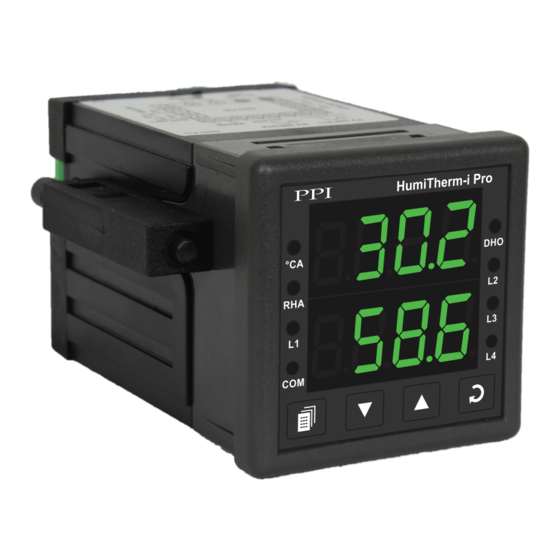
Page 3: Front Panel Layout
HumiTherm-i Pro User Manual Section 1 FRONT PANEL LAYOUT The indicator front panel comprises of digital readouts, LED indicators and membrane keys as shown in Figure 1.1 below. Figure 1.1 HumiTherm-i Pro Upper Readout Temperature Alarm De-Humidifier Indicator Output Indicator °CA... - Page 4 HumiTherm-i Pro User Manual KEYS There are four tactile keys provided on the front panel for configuring the controller and setting-up the parameter values. The Table 1.2 below lists each key (identified by the front panel symbol) and the associated function.
-
Page 5: Basic Operation
HumiTherm-i Pro User Manual Section 2 BASIC OPERATIONS POWER-UP Upon power-up, all displays and indicators are lit on for approximately 3 seconds. This is followed by the indication of the indicator model name (HUm.i) on the Upper Readout and the loaded firmware version on the Lower Readout, for approximately 1 second. - Page 6 HumiTherm-i Pro User Manual Table 2.2 Message Error Type Cause Over-range Wet Bulb Temperature above Max. Range Wet Bulb Temperature below Min. Range Under-range Sensor Open Wet Bulb Sensor (RTD) Broken / Open This error is indicated in the following cases : •...
- Page 7 HumiTherm-i Pro User Manual Table 2.3 Settings Parameter Description (Default Value) MAXIMUM DRY BULB TEMPERATURE VALUE View Only This parameter indicates the Maximum value attained by the Dry- Bulb Temperature. This is a read only value. MINIMUM DRY - BULB...
-
Page 8: Setup Mode : Access And Operation
HumiTherm-i Pro User Manual Section 3 SET-UP MODE : ACCESS AND OPERATION The various parameters are arranged in different groups, called PAGES, depending upon the functions they represent. Each group is assigned a unique numeric value, called PAGE NUMBER, for its access. - Page 9 HumiTherm-i Pro User Manual MASTER LOCKING The indicator facilitates locking all the PAGES (except Operator PAGE) by applying Master Lock Code. Under Locking, the parameters are available for view only and cannot be adjusted. The Master Lock, however does not lock the operator parameters.
-
Page 10: Page-10 : Temperature - Alarm Parameters
HumiTherm-i Pro User Manual Section 4 PAGE-10 : TEMPERATURE - ALARM PARAMETERS Table 4.1 Settings Parameter Description (Default Value) TEMPERATURE ALARM TYPE None Alarm activation is disabled. None Process Low Process Low The Alarm activates when the Temperature Value equals or falls Process High below the ‘Alarm Setpoint’... -
Page 11: Page-11 : Relative Humidity - Alarm Parameters
HumiTherm-i Pro User Manual Section 5 PAGE-11 : RELATIVE HUMIDITY - ALARM PARAMETERS Table 5.1 Settings Parameter Description (Default Value) %RH ALARM TYPE None Disable the Alarm. None Process Low Process Low The Alarm activates when the %RH Value equals or falls below the Process High ‘Alarm Setpoint’... -
Page 12: Page-12 : Input Channel Configuration Parameters
HumiTherm-i Pro User Manual Section 6 PAGE-12 : INPUT CHANNEL CONFIGURATION PARAMETERS Table 6.1 Settings Parameter Description (Default Value) INPUT TYPE FOR TEMP SENSOR Refer Table 6.1 (Default : RTD) Select Input type in accordance with the type of Temperature sensor / transmitter connected. - Page 13 HumiTherm-i Pro User Manual Settings Parameter Description (Default Value) INPUT TYPE FOR HUMIDITY SENSOR Refer Table 6.1 (Default : 0 to 5 V) Select Input type in accordance with the type of Humidity sensor / transmitter connected. Input Type Settings...
- Page 14 HumiTherm-i Pro User Manual Table 6.2 Option Resolution Range (Min. to Max.) What it means 3-wire, RTD Pt100 -199.9 to +600.0 °C / -199.9 to 999.9 °F 0.1 °C / °F 0 to 20mA DC current 4 to 20mA DC current...
-
Page 15: Page-13 : Supervisory Parameters
HumiTherm-i Pro User Manual Section 7 PAGE-13 : SUPERVISORY PARAMETERS Table 7.1 Settings Parameter Description (Default Value) UNIT SELECTION FOR TEMPERATURE °C °F Select Temperature Units in °C or °F. (Default : °C DRY-BULB TEMPERATURE AND % RH MIN / MAX MONITORING Set this parameter value to ‘Yes’... -
Page 16: Page-14 : De-Humidifier Control Parameter
HumiTherm-i Pro User Manual Section 8 PAGE-14 : DE-HUMIDIFIER CONTROL PARAMETERS Table 8.1 Settings Parameter Description (Default Value) DE-HUMIDIFIER CONTROL Disable Set this parameter to Enable if Humidifier Control is desired. If Enable enabled, the measured %RH value is compared with the set value and a relay output is switched. -
Page 17: Mechanical Installation
HumiTherm-i Pro User Manual Section 9 MECHANICAL INSTALLATION OUTER DIMENSIONS AND PANEL CUTOUT The Figure 9.1 shows the controller outer dimensions. Figure 9.1 48mm 94mm (1.89in) (3.70in) HumiTherm-i Pro °CA 7mm (0.276in) Front View Side View PANEL CUTOUT The Figure 9.2 shows the panel cutout requirements for a single controller. - Page 18 HumiTherm-i Pro User Manual PANEL MOUNTING Follow the steps below for mounting the controller on panel: 1. Prepare a square cutout to the size shown in Figure 9.2. 2. Remove the Panel Mounting Clamp from the controller Enclosure and insert the rear of the controller housing through the panel cutout from the front of the mounting panel.
-
Page 19: Electrical Connections
HumiTherm-i Pro User Manual Section 10 ELECTRICAL CONNECTIONS WARNING MISHANDLING / NEGLIGENCE CAN RESULT IN PERSONAL DEATH OR SERIOUS INJURY. 1. The user must rigidly observe the Local Electrical Regulations. 2. Do not make any connections to the unused terminals for making a tie-point for other wires (or for any other reasons) as they may have some internal connections. - Page 20 HumiTherm-i Pro User Manual DESCRIPTIONS TEMP INPUT : RTD Pt100, 3-Wire / mA / V (Terminals 17, 16, 15) RH INPUT : RTD Pt100, 3-Wire / mA / V (Terminals 14, 13, 12) Figure 10.2 (a) : RTD Input Figure 10.2 (b) : mA / V Input...
- Page 21 HumiTherm-i Pro User Manual Relay Output Potential-free Relay changeover contacts NO (Normally Open) and C (Common) rated 10A/240 VAC (resistive load). SSR Output Connect (+) and (-) terminals of SSR to (+) and (-) terminals of controller, respectively. Use Zero-Crossover, 3 to 30 VDC operated SSR.
- Page 22 HumiTherm-i Pro User Manual 85~264 VAC : Power Supply (Terminals 1, 2) The controller is supplied with power connections suited for 85 to 264 VAC line supply. Use well-insulated copper conductor wire of the size not smaller than 0.5mm for power supply connections. Connect Line (Phase) supply line to terminal 1 and the Neutral (Return) supply line to terminal 2 as shown in Figure 10.5 below.
- Page 23 HumiTherm-i Pro User Manual Process Precision Instruments 101, Diamond Industrial Estate, Navghar, Vasai Road (E), Dist. Palghar - 401 210.Maharashtra, India Sales : 8208199048 / 8208141446 Support : 07498799226 / 08767395333 sales@ppiindia.net, support@ppiindia.net w w w . p p i i n d i a . n e t...
Need help?
Do you have a question about the HumiTherm-i Pro and is the answer not in the manual?
Questions and answers