Advertisement
Quick Links
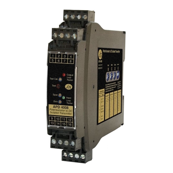
Potentiometer Input to DC Transmitters, Isolated, Field Rangeable
100 Ω to 1 MΩ Potentiometers, 0 to 90% Offset
Input:
Output:
0-1 V to ±10 VDC, or 0-2 mA to 20 mADC
O One Minute Setup for Hundreds of I/O Ranges
O External Switches & Table for Range Selection
O Removable Plugs for Faster Installation
O Full 1200 V Input/Output/Power Isolation
O Input and Output LoopTracker
LEDs
®
O Functional Output Test Button
O Selectable Sink/Source for Current Output
Applications
Q Over, Under, Out-of-Range Position Monitoring
Q Remote Control of Positioning Devices
Q Simplify Control of Potentiometer Outputs
Potentiometer Input
Field selectable ranges via switch settings
See table for complete listing
3 wire connection required
0-100 Ω
Minimum:
Maximum:
0-1 MΩ
Input span:
10-100% of potentiometer range
Input offset:
0-90% in 10% increments
Input Impedance
10 MΩ minimum
Common Mode Rejection
120 dB minimum
LoopTracker
Variable brightness LEDs indicate I/O level and status
DC Output Ranges
Field selectable ranges via switch settings
See table for complete listing
Voltage:
0-1 VDC to 0-10 VDC, 10 mA max
Bipolar voltage:
±5 VDC or ±10 VDC
Current:
0-2 mADC to 0-20 mADC
20 V compliance, 1000 Ω at 20 mA
Output Logic
Normal
Output Calibration
Multi-turn zero and span potentiometers
±15% of span adjustment range typical
Output Loop Power Supply
20 VDC nominal, regulated, 25 mADC, <10 mV
May be selectively wired for sinking or sourcing mA output
Output Test
Front button sets output to test level when pressed
Potentiometer adjustable 0-100% of span
Output Ripple and Noise
Less than 10 mV
RMS
Linearity
Better than ±0.1% of span
Ambient Temperature Range and Stability
–10°C to +60°C operating ambient
Better than ±0.02% of span per °C stability
Response Time
70 milliseconds typical
1 millisecond typical with DF option
Isolation
1200 V
minimum
RMS
Full isolation: power to input, power to output, input to output
Housing and Connectors
IP 40, requires installation in panel or enclosure
For use in Pollution Degree 2 Environment
Mount vertically to a 35 mm DIN rail
Four 4-terminal removable connectors, 14 AWG max wire size
Power
85-265 VAC, 50/60 Hz or 60-300 VDC, 2 W maximum
D versions: 9-30 VDC or 10-32 VAC 50/60 Hz, 2 W maximum
A
P
BSOLUTE
ROCESS
File E145968
85-265 VAC, 60-300 VDC
model only
H H H H H H
H H H H H
H H H H H H
H H H H H
H H H H H H
H H H H H
H H H H H H
H H H H H
H H H H H H
Made in USA
Free Factory
I/O Setup!
1
Minute
Setup!
Dimensions
0.89" W x 4.62" H x 4.81" D
22.5 mm W x 117 mm H x 122 mm D
Height includes connectors
Description
The APD 4008 accepts a resistance input from potentiometer,
slidewire, linear position, displacement, or rotational devices
and provides an optically isolated DC voltage or current output
that is linearly related to the potentiometer position.
The APD 4008 will accept any potentiometer with a value of
0-100 Ω through 0-1 MΩ without recalibration and without
max. ripple
RMS
affecting accuracy. The APD 4008 output can be field-con-
figured via external rotary and slide switches. Offsets and/or
input ranges other than 0 to 100% of the potentiometer range
can also be selected.
The full 3-way (input, output, power) isolation makes this mod-
ule useful for ground loop elimination, common mode signal
rejection or noise pickup reduction.
Sink/Source Output
The APD 4008 has a 20 VDC loop excitation supply for the
output. This power supply can be used to power a passive mA
How to Order
All models are field rangeable
Models can be pre-set to your specifications.
Order APD 4008 D for operation on low voltage power.
Model
APD 4008
Field configurable—specify range if
APD 4008 D
Options–add to end of model number
DF
Fast response time, consult factory. DF option will
cause output noise levels to be greater than
standard specifications.
U
Conformal coating for moisture resistance
I
NSTRUMENTS
Connect mA Output
for Sink or Source
5 6 7 8
Output LoopTracker
LED
Output Test
Function
Front Zero and Span
Input LoopTracker
LED
Use Any
Potentiometer
9 10 11 12
Universal
Power
Input
Field configurable—specify range if
factory is to set switches
factory is to set switches
1220 American Way Libertyville, IL 60048
Phone:
800-942-0315
Fax: 800-949-7502
APD 4008
1 2 3 4
13 14 15 16
device. If not required, the APD 4008 output can be wired as
a passive output. Sinking/sourcing versatility allows the APD
4008 to produce a powered or unpowered mA output allowing
it to work with powered or unpowered mA devices.
LoopTracker
API exclusive features include two LoopTracker LEDs (green for
input, red for output) that vary in intensity with changes in the
process input and output signals. These provide a quick visual
picture of your process loop at all times and can greatly aid in
saving time during initial startup and/or troubleshooting.
Output Test
An API exclusive feature includes the test button to provide a
fixed output (independent of the input) when held depressed.
The test output level is potentiometer adjustable from 0 to
100% of output span.
The output test button greatly aids in saving time during initial
startup and/or troubleshooting.
Please specify
Model
Input range (if factory is to pre-set)
Output range (if factory is to pre-set)
Options as required
Output
85-265 VAC, 50/60 Hz or
9-30 VDC or 10-32 VAC
Accessory—order as separate line item
API BP4 Spare 4-terminal plug, black
api-usa.com
Removable Plugs
See Wiring
Diagrams on
Next Page
Power
60-300 VDC
© 10-18
Advertisement

Related Manuals for Absolute Process Instruments APD 4008


Summary of Contents for Absolute Process Instruments APD 4008
- Page 1 20 V compliance, 1000 Ω at 20 mA Output Logic Description device. If not required, the APD 4008 output can be wired as Normal The APD 4008 accepts a resistance input from potentiometer, a passive output. Sinking/sourcing versatility allows the APD...
- Page 2 For most applications 0-100% of the potentiometer range is bleshooting. When released, the output will return to normal. Powered used. The APD 4008 can be set up to use part of the potenti- Current Sinking Output 4-20 mA The Test Cal. potentiometer can be used to set the test output switch E set to “I”...
- Page 3 Switch Settings APD 4008 APD 4008 Range Selection Table The module side label lists common ranges. Use the table Switch B controls the percent of potentiometer range to use. For ranges that fall between the listed ranges use the next below for a complete selection of I/O ranges for your applica- Switch C controls the percent of input offset.
- Page 4 Installation APD 4008 Mounting to a DIN Rail Installation Removal Avoid shock hazards! Turn signal input, output, and power off Install module vertically on a 35 mm DIN rail in a protective before removing module. enclosure away from heat sources. Do not block air flow. Allow 1"...
Need help?
Do you have a question about the APD 4008 and is the answer not in the manual?
Questions and answers