Table of Contents
Advertisement
Quick Links
Firmware: up to v. 5.22
•
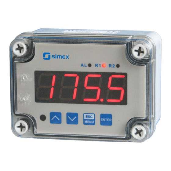
Input type: 0/4-20 mA, 0/1-5V, 0/2-10V
•
Wall mounting case IP 65
•
Read the user's manual carefully before starting to use the unit or software.
Producer reserves the right to implement changes without prior notice.
2013.08.14
User manual
METER
SRP-N118
Assisting the automation
industry since 1986
SRP-N118_INSSXEN_v.2.08.002
Advertisement
Table of Contents

Subscribe to Our Youtube Channel
Related Manuals for Simex SRP-N118


Summary of Contents for Simex SRP-N118
- Page 1 Assisting the automation industry since 1986 User manual METER SRP-N118 Firmware: up to v. 5.22 • Input type: 0/4-20 mA, 0/1-5V, 0/2-10V • Wall mounting case IP 65 • Read the user's manual carefully before starting to use the unit or software.
-
Page 2: Table Of Contents
User manual - METER SRP-N118 CONTENTS 1. BASIC REQUIREMENTS AND USER SAFETY..................3 2. GENERAL CHARACTERISTICS.........................4 3. TECHNICAL DATA............................4 4. DEVICE INSTALLATION..........................6 4.1. UNPACKING............................6 4.2. ASSEMBLY............................6 4.3. CONNECTION METHOD........................7 4.4. MAINTENANCE..........................14 5. FRONT PANEL DESCRIPTION........................14 6. PRINCIPLE OF OPERATION........................15 6.1. MEASUREMENT MODE........................15... -
Page 3: Basic Requirements And User Safety
User manual - METER SRP-N118 Explanation of symbols used in the manual: - This symbol denotes especially important guidelines concerning the installation and operation of the device. Not complying with the guidelines denoted by this symbol may cause an accident, damage or equipment destruction. -
Page 4: General Characteristics
To allow user to change presets without opening the cover, an IR sensor is mounted. Remote controller keyboard is equivalent to the device keyboard (Note, that remote controller is not a part of the SRP-N118 set – it is an additional equipment). - Page 5 User manual - METER SRP-N118 Current input resistance < 65 Ω (typical 55 Ω) Voltage input 0÷5 V, 1÷5 V, 0÷10 V, 2÷10 V Voltage measurement accuracy ± 0,1% @ 25°C; ± one digit (for 0÷10 V range) Voltage input resistance >...
-
Page 6: Device Installation
User manual - METER SRP-N118 insulation resistance: >20MΩ insulation strength between power supply and input/output terminal: 1min. @ 2300V insulation strength between relays terminal: 1min. @ 1350V according to: PN-EN 61326-1 This is a class A unit. In a residential or a similar area it can cause radio frequency interference. -
Page 7: Connection Method
User manual - METER SRP-N118 110 mm 67 mm 90 mm Figure 4.1. Device and assembly dimensions 4.3. CONNECTION METHOD Caution - Installation should be conducted by qualified personnel . During installation all available safety requirements should be considered. The fitter is responsible for executing the installation according to this manual, local safety and EMC regulations. - Page 8 User manual - METER SRP-N118 - Unused terminals (marked as n.c.) must not be used for connecting any connecting cables (e.g. as bridges), because this can cause damage to the equipment or electric shock. - If the unit is equipped with housing, covers and sealing to, protecting against water intrusion, pay special attention to their correct tightening or clamping.
- Page 9 User manual - METER SRP-N118 0/1 - 5V 0/2 - 10V 12 11 10 9 8 5 4 3 n.c. n.c. DATA- 24V ±3V 0/4 - 20mA Imax = 25 mA DATA+ (optional) (optional) (depending on version) Figure 4.3. Terminals description (relay outputs)
- Page 10 User manual - METER SRP-N118 internally connected 24V DC 12 11 10 9 8 7 6 12 11 10 9 8 7 6 Figure 4.6. Connection of 3-wire current converters internally connected 24V DC 12 11 10 9 8 7 6 12 11 10 9 8 7 6 Figure 4.7.
- Page 11 User manual - METER SRP-N118 on the load. In consequence of using the suppression circuit, the level of generated electromagnetic disturbances is lower, and the life of relay contacts rises. Figure 4.9. Examples of suppression circuit connection: a) to relay terminals; b) to the inductive load...
- Page 12 Figure 4.11. Connections of 2-wire sensor: a) active, b) passive (needs additional supply) SRP-N118 meter has no galvanic separation between measurement input and RS- 485 interface. If serial connection of multiple units is made or serial connection with other device, without galvanic separation of RS-485 interface, is made then RS-485 interface separators must to be used certainly (Figure 4.12, 4.13).
- Page 13 11 10 9 8 7 6 galvanic insulation Figure 4.13. Serial connection of passive 2-wire sensor with SRP-N118 unit and other current measurement device (e.g. PLC controller). If device B (Figure 4.12 , 4.13) is equipped with galvanic separated input or if different potentials between A and B devices signal grounds are allowed (e.g.
-
Page 14: Maintenance
User manual - METER SRP-N118 −U S min. R −R −R B max. W max. INP. For example if U =12V then: S min. 24−12 R −50−30=520 B max. W max. 0,02 4.4. MAINTENANCE The unit does not have any internal replaceable or adjustable components available to the user. -
Page 15: Principle Of Operation
User manual - METER SRP-N118 Symbol used in the manual: [ENTER] ENTER Functions : • Start to edit the parameter • Enter to the sub-menu, • Confirmation of changes made in parameter being edited Symbol used in the manual: [^] [v] Functions : •... -
Page 16: Detection Of The Peak Values
Configuration of the device (via menu or RS-485 interface) do not stops measures. 6.2. DETECTION OF THE PEAK VALUES The SRP-N118 controller is equipped with peaks detection function. It can detect a peaks of the input signal and display their values. Presets connected with this function are placed in ”HOLd”... -
Page 17: Control Of The Relay Outputs
User manual - METER SRP-N118 6.3. CONTROL OF THE RELAY OUTPUTS The control of the object (measured signal) is realized via relay outputs. Front panel LEDs named „R” indicates the state of particular relay output. If device is not equipped with one or more relay outputs, menus refer to this relays are available, but apply to LED indicators only. -
Page 18: One Threshold Mode
User manual - METER SRP-N118 6.3.1. One threshold mode Figure 6.6 presents the principle of relay outputs operation for one threshold mode, and an example values of other parameters. measured “SEtP” parameter displayed value signal (expected signal value) zone A “HYSt”... -
Page 19: Two Thresholds Mode
User manual - METER SRP-N118 The state of relay output while the input value exceeds the border values (points A, B, C, D) is described by parameter “modE”. The relay can be turned on (“modE” = ”on”), or turned off (“modE” = ”oFF”) when input signal value is contained in zone A (Figure 6.6 a). -
Page 20: Device Programming
User manual - METER SRP-N118 “HYSt”, “modE”, “t on”, “toFF”, “unit” and “AL” are connected with both “SEtP” and “SEt2” thresholds. While the controlling process, the relay output changes his state depends of both “SEtP” and “SEt2” thresholds in similar way as it was described in one threshold mode. -
Page 21: Parameters Edition
User manual - METER SRP-N118 Functions of the buttons while sub-menu and parameters choice: Selection of sub-menu or parameter for editing. Name of selected item (sub- menu or parameter) is displayed. Operation of [ENTER] button depend on present menu position: ENTER •... -
Page 22: Switch Parameters ("List" Type)
User manual - METER SRP-N118 Press [ENTER] at least 2 seconds to accept the changes, after that question ”Set?” is displayed, and user must to confirm (or cancel) the changes. To conform changes (and story it in EEPROM) press [ENTER] button shortly after ”SEt?” is displayed. To cancel the changes press [ESC] button shortly after ”SEt?”... - Page 23 User manual - METER SRP-N118 If there are few relay outputs available, then every output has its own configuration menu (e.g. menu „rEL2” for relay (LED) „R2”). Principle of the relays operation is described in paragraph CONTROL OF THE RELAY OUTPUTS.
- Page 24 User manual - METER SRP-N118 HYSt”, and turned on when the input signal is contained in the second zone. The bigger threshold means bigger one of “SEtP” and “SEt2” thresholds, the lower threshold” means lower one of “SEtP” and “SEt2” thresholds.
-
Page 25: Inpt" Menu
User manual - METER SRP-N118 7.3.2. “inPt” menu This menu presets the measurement input: “tYPE" - type of the input / sensor. This parameter can be set to values: ”0-20”, “4-20” - current inputs. ”0-10”, “2-10”, ”0-5”, “1-5” - voltage inputs. - Page 26 User manual - METER SRP-N118 a) for the cylindrical tank in the vertical position: „t h1” - the height of the bottom part of a tank (in the elliptic paraboloid shape), this parameter has the fixed precision - 2-decimal point, „t h2”...
- Page 27 User manual - METER SRP-N118 volume of the tank can be achieved by eg. such middle-current range, If the measurement value do not exceeds permissible measurement range • but displayed value exceeds range of 9999 than you can move to the right position of the decimal point if it is still possible (see parameter Menu- >”inPt”->”Pnt”).
- Page 28 User manual - METER SRP-N118 t h1 t h2 t h3 t Sh h~I[mA] t Sn Figure 7.2 Parameters of cylindrical tank in horizontal position. If user defined characteristic is selected (parameter “CHAr” = ”USEr”) the parameters „Lo C” and „Hi C” are not available for modification, due to their values are calculated from defined characteristic.
- Page 29 User manual - METER SRP-N118 characteristic is displayed for about approx. 1.5 sec. After that device waits for selection of point being edited (by [^], [v] buttons). The short pressing of [ENTER] button causes by switching between X and Y value of the displayed point. The long press (press and hold at least 2 sec) of [ENTER] button causes by entering to edit the selected coordinate of the point.
-
Page 30: Bri" Parameter
User manual - METER SRP-N118 procedure of the permissible input range determining is presented in details. If the measurement value do not exceeds permissible measurement range but displayed value exceeds range -999 ÷ 9999, the warning is displayed rather ”-Ov-”... -
Page 31: Rs" Menu
User manual - METER SRP-N118 The “one-use password” can be used ONE TIME ONLY, it is impossible to use it again! The “one-use password” can be restored by Service Division only. “A r1, A r2” - this option permits user (”on”) or prohibits (”oFF”) to modify the thresholds of the relays/LEDs R1, R2 without knowledge about user password. -
Page 32: Edit" Parameter
User manual - METER SRP-N118 “38.4” “57.6” “115.2” ”bAud” parameter ”rESP” parameter “ 10c” “ 20c” “ 50c” Tab.7.1. Settings of ”rESP” parameter 7.3.7. ”Edit” paramet er This parameter allows to change the edition mode of numerical parameters: ”dig” - the change to “by digit” mode, ”Slid”... -
Page 33: Menu Structure
User manual - METER SRP-N118 7.4. MENU STRUCTURE Measurement mode Press and hold at least 2 seconds MENU MENU 4-digit user password entering (if it is different from „0000”) 0 _ _ _ ENTER ENTER ENTER Parameter MENU rEL1 SEtP... - Page 34 User manual - METER SRP-N118 See previous page ENTER ENTER Parameter MENU modE HOLd edition ENTER MENU timE Hdis MENU H r1 H r2 ENTER ENTER Parameter MENU SECu Scod edition ENTER MENU A r1 MENU A r2 ENTER ENTER...
-
Page 35: The Alarm Led
User manual - METER SRP-N118 8. THE ALARM LED The ALARM LED (AL) is turned on when input signal is out of the permissible input range. See parameters: “tyPE”, “Lo r” and “Hi r” in paragraph „InPt” menu. 9. OVER-CURRENT PROTECTION The current input of the device is equipped with over-current protection circuit. -
Page 36: Linear Characteristic
User manual - METER SRP-N118 10.1.1. Linear characteristic The normalized result is converted by fixed coefficients determined by “Lo C” and “Hi C” parameters (when the normalized results is equal 0, then value “Lo C” is displayed, and when the normalized results is equal 1, then value “Hi C” is displayed). Expression presented below... -
Page 37: Square Root Characteristic
User manual - METER SRP-N118 10.1.3. Square root characteristic The normalized result is rooted and further conversion is done as for linear characteristic. Conversion is made accordingly with the expression: × "Hi C" −"Lo C" "Lo C" , where W means the displayed value. -
Page 38: Volume Characteristics Of A Cylindrical Tank
User manual - METER SRP-N118 Normalized measurement I (for 0-20 mA range) 0,35 5-elements characteristic X (PH) = „70.0.” Y (PH) X = „35.0.” Y (PL) X (PL) = „50.0.” X = „20.0.” Prąd wejściowy [mA] X = „90.0.” X = „100.0.”... -
Page 39: Examples Of Calculations
User manual - METER SRP-N118 Volume of tank can be write by general formula: ∫ ⋅dh Possible combination of tank shape for calculation the volume: cylindrical tank in vertical position cylindrical tank in horizontal position parameter t h2=0 t h3=0... - Page 40 User manual - METER SRP-N118 Example 3: The linear characteristic Let the input mode = 4-20 mA, and parameters “Lo C” and “Hi C” equal to -300 and 1200 respectively. The calculations will be done for three different input currents from example 2.
- Page 41 User manual - METER SRP-N118 Example 6: The user defined characteristic Let the input mode = 4-20 mA, and the user selected the 10 segment characteristic. To do this it is necessary to enter X and Y coordinates of 11 points (see Menu ”inPt”).
- Page 42 User manual - METER SRP-N118 „t Sn”=00,00 „t Sh”=10,00 „t h1”=00,00 „t h2”=10,00 „t h3”=00,00 „t d”=04,00 Input current [mA] Figure 10.6 The volume characteristic of tank depending on input current in 4÷20mA range. Example 8: Volume characteristics of a cylindrical tank in the horizontal position We assume that the user has tank for wheat in the shape of the cylinder located in horizontal position.
-
Page 43: The Modbus Protocol Handling
User manual - METER SRP-N118 I [mA] Figure 10.7 The volume characteristic of tank depending on input current in 4÷20mA range. 11. THE MODBUS PRO TOCOL HANDLING Transmission parameters: 1 start bit, 8 data bits, 1 or 2 stop bit (2 bits are send, 1 and 2 bits... -
Page 44: List Of Registers
User manual - METER SRP-N118 11.1. LIST OF REGISTERS Register Write Range Register description -999 ÷ 9999 Measurement value (no decimal point) The status of the current measurement; 0h - data valid; A0h - top 0h, A0h, 60h border of the measurement range is exceeded; 60h - bottom border of the measurement range is exceeded;... - Page 45 User manual - METER SRP-N118 Register Write Range Register description “mbAc” parameter in “rS” menu (permission to write registers via 0 ÷ 1 RS-485 interface); 0 - write denied ; 1 - write allowed Parameters of “SECU” menu (binary format (0 - „oFF”, 1 - „on”): see descr.
-
Page 46: Transmission Errors Description
User manual - METER SRP-N118 Register Write Range Register description “modE” parameter in “HOLd” menu (type of detected changes): 0 ÷ 1 0 - peaks; 1 - drops “PEA” parameter in “HOLd” menu (minimum detectable change, no 0 ÷ 9999 decimal point included) “timE”... -
Page 47: Examples Of Query/Answer Frames
Data byte count in answer frame DATA H,L Data byte (Hi and Lo byte) CRC L,H CRC error check (Hi and Lo byte) 1. Read of the displayed value (measurement), SRP-N118 device address = 01h: ADDR FUNC REG H,L COUNT H,L... - Page 48 User manual - METER SRP-N118 3. Change of the device address from 1 to 2 (write to reg. 20h) ADDR FUNC REG H,L DATA H,L CRC L,H DATA H - 0 DATA L - new device address (2) The answer (the same as the message):...
-
Page 49: Default And User's Settings List
User manual - METER SRP-N118 12. DEFAULT AND USER'S SETTINGS LIST Desc. Parameter Description Default value User's value page Parameters of relay R1 operation (“rEL1” menu) SEtP Relay R1 threshold 20.0 SEt2 Relay R1 second threshold 40.0 HYSt Hysteresis of relay R1... - Page 50 User manual - METER SRP-N118 Desc. Parameter Description Default value User's value page Hi r Extension of the top of the nominal input range 5.0 (%) Display parameters Display brightness bri6 Configuration of peaks detection function (“HOLd” menu) modE Kind of detected changes...
- Page 51 User manual - METER SRP-N118...
- Page 52 SIMEX Sp. z o.o. ul. Wielopole 7 80-556 Gdańsk Poland tel.: (+48 58) 762-07-77 fax: (+48 58) 762-07-70 http://www.simex.pl e-mail: info@simex.pl...
Need help?
Do you have a question about the SRP-N118 and is the answer not in the manual?
Questions and answers