Table of Contents
Advertisement
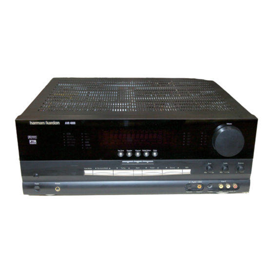
AVR 4000 Audio/Video Receiver
OWNER'S MANUAL
•
•
•
•
• 5CH STEREO
Power
Phones
AVR 4000
• HALL 1
DTS
MUTE
DIGITAL
• HALL 2
DOLBY D
PRO LOGIC
• THEATER
PCM
MP3
3 STEREO
• VMAx
• LOGIC 7
• SURR. OFF
Tone Mode
Surround Mode
AUTO
TUNED ST
MEMORY PRESET
RDS
PTY
CT
RT
TA
OPTICAL
1 2 3
COAXIAL
1 2 3
ANALOG
VMAx NF
5.1 LOGIC 7 CM
PRO LOGIC
3-STEREO
5 CH STEREO HALL 12
DIGITAL
Test Tone
Speaker
Channel
Digital Select
Set
Tuning
Band
Preset
• VID 1
• CD
O
O
L
0
C
0
R
SLEEP
• VID 2
• TAPE
O
O
• VID 3
• FM
O
O
LS
LFE
RS
• VID 4
• AM
OSD
O
O
NIGHT
MULTI
THEATER
• DVD
• 6 CH.
Delay
Source
RDS
In – DIgital – In/Out
Optical 3 Coaxial 3
Power for the Digital Revolution
Bass
Min
Max
S-Video
®
™
Advertisement
Chapters
Table of Contents

Related Manuals for Harman Kardon AVR 4000


Summary of Contents for Harman Kardon AVR 4000
- Page 1 AVR 4000 Audio/Video Receiver OWNER’S MANUAL AVR 4000 • • HALL 1 • DIGITAL • HALL 2 • PRO LOGIC • THEATER • 3 STEREO • VMAx • 5CH STEREO • LOGIC 7 • SURR. OFF Power Phones AUTO TUNED ST...
-
Page 2: Table Of Contents
– (number in an oval) indicates a button or indicator on the remote – (letter in a square) indicates an indicator in the front-panel display – (letter in an oval) indicates a button on the Zone II remote Carsten Olesen Harman Kardon Europe A/S 09/00... -
Page 3: Introduction
DVD and LD releases and Digital Television broadcasts. While complex digital systems are hard at work within the AVR 4000 to make all of this happen, hookup and operation are simple. Color-keyed connections, programmable remote control, and on-screen menus make the AVR 4000 easy to use. -
Page 4: Safety Information
Safety Information Important Safety Information Verify Line Voltage Before Use Your AVR 4000 has been designed for use with 220-240-Volt AC current. Connection to a line voltage other than that for which it is intended can create a safety and fire hazard and may damage the unit. -
Page 5: Front Panel Controls
System Power Control: When the Main Power Switch is “ON, ” press this button to turn on the AVR 4000; press it again to turn the unit off (to Standby). Note that the Power Indicator surrounding the switch will turn green when the unit is on. - Page 6 RDS Select Button: Press this button to dis- play the various messages that are part of the RDS data system of the AVR 4000’s tuner. (See page 34 for more information on RDS). Digital Optical 3 Input: Connect the opti- cal digital audio output of an audio or video prod- uct to this jack.
-
Page 7: Front Panel Information Display
Theater Mode Indicator: This indicator illu- minates to show that the Theater mode is in use. Night Mode Indicator: This indicator lights when the AVR 4000 is in the Night mode, which preserves the dynamic range of digital program material at low volume levels. - Page 8 Mute Indicator: This indicator illuminates to remind you that the AVR 4000’s output has been silenced by pressing the Mute button . Press the Mute button again to return to the previously selected output level.
-
Page 9: Rear Panel Connections
CD Inputs: Connect these jacks to the ana- log output of a compact disc player or CD changer. · ° AC INPUT ~230V/50Hz A MODEL NO. AVR 4000 NORTHRIDGE CALIFORNIA, USA MADE IN CHINA AC OUTLETS ~230V/50Hz UNSWITCHED / 100W MAX SWITCHED / 50W MAX –... - Page 10 (+) terminals on the AVR 4000 to the red (+) terminals on the speaker and the black (–) ter- minals on the AVR 4000 to the black (–) termi- nals on the speakers.
-
Page 11: Main Remote Control Functions
Main Remote Control Functions Power On Button IR Transmitter Window Program/SPL Indicator Power Off Button Input Selectors AVR Selector AM/FM Tuner Select Learn Button Test Button Sleep Button Surround Mode Selector Night Mode Channel Select Button Buttons Button Set Button Digital Select Numeric Keys Tuner Mode... -
Page 12: Power On Button
Input Selectors. The descriptions shown here primarily detail the functions of the remote when it is used to operate the AVR 4000. (See page 44 for information about alternate functions for the remote’s buttons.) - Page 13 RDS Select Button: Press this button to display the various messages that are part of the RDS data system of the AVR 4000’s tuner. (See page 34 for more information on RDS). Preset Up/Down: When the tuner is in use, press these buttons to scroll through the stations programmed into the AVR 4000’s mem-...
-
Page 14: Zone Ii Remote Control Functions
AVR 4000’s Multi IR input jack b. When it is used in the same room as the AVR 4000, it will control the functions of the AVR 4000 or any compatible Harman Kardon products in that room. -
Page 15: Installation And Connections
2. Connect the analog Play/Out jacks of a cas-... - Page 16 Video signal to S-Video or vice versa. Thus both connections must be made from the AVR 4000 to the TV if both, Video and S-Video sources, are used, and the appropriate input on the TV must be selected.
-
Page 17: System And Power Connections
TV must be made manually. System and Power Connections The AVR 4000 is designed for flexible use with multiroom systems, external control components and power amplifiers. Main Room Remote Control Extension... - Page 18 Option 1: Use high-quality, shielded stereo audio interconnect cable with phono plugs on both ends from the AVR 4000’s location to the remote room. At the remote room, connect the interconnect cable to a stereo power amplifier.
-
Page 19: System Configuration
System Configuration When all audio, video and system connections have been made, there are a few configuration adjustments that must be made. A few minutes spent to correctly configure and calibrate the unit will greatly add to your listening experience. Speaker Selection No matter which type or brand of speakers is used, the same model or brand of speaker... -
Page 20: First Turn On And Use Of Osd
You are now ready to power up the AVR 4000 to begin these final adjustments. 1. Plug the Power Cable into an un- switched AC outlet. -
Page 21: Input Setup
However, to make it easier to establish the initial parameters for the AVR 4000, it is best to select Dolby Pro Logic for most analog inputs and Dolby Digital for inputs connected to digital sources. In the... - Page 22 S U B, which is the “on” position. If the front left/right speakers are set to LARGE, three options are available: • If no subwoofer is connected to the AVR 4000, press the buttons on the remote so that N O N E appears in the on-screen menu.
-
Page 23: Adjustments For Other Inputs
System Configuration 40Hz, choose the frequency that is closest to the upper frequency limit of your subwoofer. This fig- ure is normally printed in the Owner’s Manual or data sheet for the speakers, or consult the speak- er’s manufacturer. • When the front speakers have been set to LARGE, the crossover choices are 4 0 H z or 6 0 H z to match the typical crossover points of full range speakers. -
Page 24: Night Mode Settings
Output level adjustment is a key part of the con- figuration process for any surround sound prod- uct. It is particularly important for a Dolby Digital receiver such as the AVR 4000, as correct out- puts will ensure that you hear sound tracks with the proper directionality and intensity. -
Page 25: Using Ezset
EzSet Sensor Microphone at the top of the remote and aim it at the AVR 4000, not vertically (like you’d do with a microphone). 6. Press and hold the SPL Indicator Select for three seconds. Release the button when... - Page 26 Adjustment procedure, see page 32, also for the Surround Off (Stereo) and VMAx modes. Once the settings outlined on the previous pages have been made, the AVR 4000 is ready for operation. While there are some additional settings to be made, these are best done after...
-
Page 27: Operation
Note that these controls are not effec- tive with the 6-Channel Direct Input. • To set the output of the AVR 4000 so that the output is “flat, ” with the Tone controls and the Balance control de-activated, press the Tone... -
Page 28: Surround Mode Chart
Operation Surround Mode Chart MODE FEATURES DOLBY DIGITAL Available only with digital input sources encoded with Dolby Digital data. It provides up to five separate main audio channels and a special dedicated Low Frequency Effects channel. Available only with digital input sources encoded with DTS data. Available on special DVD, LD and audio-only discs, DTS provides up to five separate main audio channels and a special dedicated low frequency channel. -
Page 29: Surround Mode Selection
(HDTV) system. Note that an optional, external RF demodulator is required to use the AVR 4000 to listen to the Dolby Digital sound tracks available on laser discs. Connect the RF output of the LD player to... - Page 30 Music mode for a wider front sound stage (see Surround Mode Chart page 28). MP3 Audio Playback The AVR 4000 is one of the first A/V receivers to provide on-board decoding for the MP3 audio format used on specific computer audio files and by portable MP3 players/recorders.
-
Page 31: Tape Recording
DVD player (usually with the “Audio Select” button or in a menu screen on the disc) to send a full 5.1 feed to the AVR 4000 or to select the appropriate audio track and thus lan- guage (”2.0” audio tracks can be played with all surround modes, even with Logic 7, see indicator ”PCM”... -
Page 32: Output Level Trim Adjustment
• To make an analog recording of a Dolby Digital or DTS source is not possible, if the source is con- nected to a digital input of the AVR 4000 only. But the analog two channel signal of that source can be recorded (see item 5, ”Important Notes... -
Page 33: Tuner Operation
Operation Tuner Operation The AVR 4000’s tuner is capable of tuning AM, FM and FM Stereo broadcast stations and receiv- ing RDS data. Stations may be tuned manually, or they may be stored as favorite station presets and recalled from a 30 position memory. -
Page 34: Rds Operation
Operation RDS Operation The AVR 4000 is equipped with RDS (Radio Data System), which brings a wide range of information to FM radio. Now in use in many countries, RDS is a system for transmitting station call signs or network information, a... - Page 35 These stations can be found by selecting TRAFFIC, the option in front of NEWS in the list. The AVR 4000 RDS will find the appropriate sta- tion, even if it is not broadcasting traffic infor- mation when the search is made.
-
Page 36: Advanced Features
Turn On Volume Level As is the case with most audio/video receivers, when the AVR 4000 is turned on, it will always return to the volume setting in effect when the unit was turned off. However, you may prefer to... -
Page 37: Semi Osd Settings
Note that this setting is temporary and will remain active only until it is changed or until the AVR 4000 is turned off. Once the unit is turned off, the semi-OSD displays will remain activated, even if they were switched off for the previous listening session. -
Page 38: Multiroom Operation
Selector buttons to turn on to a specific source. As long as an IR feed to the AVR 4000 has been established from the remote room, using any of... -
Page 39: Programming The Remote
”001” must be entered. Auto-Search Method If the unit you wish to include in the AVR 4000’s remote is not listed in the code tables in this manual or if the code does not seem to operate properly, you may wish to program the correct code using the Auto Search method that follows. -
Page 40: Learning Codes From A Remote
Release the buttons. It is important that you begin the next step within 20 seconds. 4. Press the button on the AVR 4000 remote that you wish to program. Note that the Program/ SPL Indicat will stop flashing. -
Page 41: Macro Programming
The red light under the Input Selector will blink and then turn off. Example: To program the Macro 1 button so that it turns on the AVR 4000, TV and a Sat- Receiver, follow these steps: • Press the Macro 1 button and Mute buttons at the same time and then release them. -
Page 42: Programmed Device Function
Some commands, such as the volume control, are the same as they are with the AVR 4000. Other buttons will change their function so that they correspond to a secondary label on the remote. -
Page 43: Channel Control Punch-Through
TV, you may wish to start or stop your VCR or DVD without having to change the device selected by the AVR 4000 or the remote. To pro- gram the remote for Transport Control Punch- Through, follow these steps: 1. -
Page 44: Function List
Function List 44 FUNCTION LIST Button Name AVR Function Power Off Power Off Power On Power On Mute Mute AVR Select DVD Input Select CD Input Select Tape Tape Input Select VID 1 Video 1 Select VID 2 Video 2 Select VID 3 Video 3 Select VID 4... - Page 45 Function List Button Name Tape Power Off Power Off Power On Power On Mute Tape Tape Select VID 1 VID 2 VID 3 VID 4 Learn AM/FM 6 Ch. Select Sleep Test Volume Up Surround Select Night Multi Room Volume Down Channel/Guide Speaker/Menu Digital/Exit...
-
Page 46: Setup Code Tables
Setup Code Table: TV Maker (Brand) Name Code Number (3digit) List AIWA 340 341 AKAI 019 049 ALBA 044 049 AMSTRAD 004 011 ARC EN CIEL 029 034 ARCAM 029 272 ASTRA ATLANTIC 050 113 AUDIOSONIC 031 076 195 BANG & OLUFSEN BARCO 310 326 BEKO... - Page 47 Setup Code Table: TV (continued) Maker (Brand) Name Code Number (3digit) List HANSEATIC 018 049 HIFIVOX 029 034 HITACHI 007 009 168 171 IMPERIAL 002 044 INTERVISION 342 343 INTERFUNK 049 063 090 117 ITT-NOKIA 090 097 171 172 018 103 KARCHER 003 020 KATHREIN...
- Page 48 Setup Code Table: TV (continued) Maker (Brand) Name Code Number (3digit) List RBM(UK) REDIFFUSION 059 105 REDIFFUSION(UK) 150 162 REDIFUSION 104 105 036 040 354 355 ROADSTAR 031 195 ROTEL 056 065 SABA 014 017 120 133 SALORA 033 075 SAMPO SAMSUNG 050 063...
- Page 49 Setup Code Table: TV (continued) Maker (Brand) Name Code Number (3digit) List WESTINGHOUSE 063 094 WESTON YOKO 050 195 ZANUSSI 036 040 Setup Code Table: VCR Maker (Brand) Name Code Number (3 digit) List AIWA 039 044 AKAI 028 035 AKURA 029 112 ALBA...
- Page 50 Setup Code Table: VCR (continued) Maker (Brand) Name Code Number (3 digit) List FISHER 008 015 FUJITSU FUNAI 039 148 GRANADA(UK) GBC(UK) 054 084 GOLDSTAR 036 055 GOODMANS 029 039 GRAETZ 044 045 GRAETZ(ITT) GRANADA 001 015 GRANADA(UK) 018 054 GRUNDIG 054 086 HANSEATIC...
- Page 51 Setup Code Table: VCR (continued) Maker (Brand) Name Code Number (3 digit) List PANASONIC 017 071 PATHE' MARCONI 044 045 PHILIPS 006 041 PIONEER 047 054 PROLINE 039 148 QUELLE 011 042 RADIOLA 049 091 060 062 REALISTIC 008 015 REDIFFUSION 004 007 ROADSTAR...
- Page 52 CAPETRONIC CROWN DENON 187 188 FISHER 023 055 FUNAI GOLDSTAR (LG) 016 087 GRUNDIG 220 224 HAITAI 099 214 HARMAN KARDON 001 002 HITACHI 049 093 029 176 KENWOOD 014 020 KYOCERA LINN LUXMAN 018 035 MAGNAVOX 039 051 MARANTZ...
- Page 53 Setup Code Table: CD (continued) Maker (Brand) Name Code Number (3 Digit) List THORENS TOSHIBA 013 074 UNIVERSUM (QUELLE) 220 222 YAMAHA 019 031 Setup Code Table: CBL Maker (Brand) Name Code Number (3digit) List BT CABLE CABLETIME 008 011 CLYDE CABLE VISION DECSAT CANAL FILMNET...
- Page 54 Setup Code Table: SAT Maker (Brand) Name Code Number (3digit) List AIWA AKAI ALBA 001 017 AMSTRAD 071 097 ANKARO 051 121 ASTRA 068 098 ASTRO 175 176 177 178 179 180 181 182 BLAUPUNKT 038 090 BRUNS BUSH 024 048 BUSH(UK) CAMBRIDGE CAMBRIDGE ARD200...
- Page 55 080 127 ZENITH Setup Code Table: DVD Maker (Brand) Name Code Number (3 Digit) List CALIFORNIA AUDIO DENON 002 019 003 004 GOLDSTAR (LG) HARMAN KARDON 001 032 KENWOOD MAGNAVOX 009 033 MARANTZ MITSUBISHI 023 036 ONKYO PANASONIC 024 025...
-
Page 56: Troubleshooting Guide
• Resume play for DVD • Check that Digital Signal is fed to the Digital Input selected To clear the AVR 4000’s entire system memory including tuner presets, output level settings, delay times and speaker configuration data, first... -
Page 57: Technical Specifications
Height measurement includes feet and chassis. All features and specifications are subject to change without notice. Harman Kardon is a registered trademark, and Power for the digital revolution is a trademark, of Harman International Industries, Inc. is a trademark of Harman International Industries, Inc. - Page 58 250 Crossways Park Drive, Woodbury, New York 11797 www.harmankardon.com Harman Consumer International: 2, route de Tours, 72500 Château-du-Loir, France © 2000 Harman Kardon, Incorporated Part No.: J90200012200...
Need help?
Do you have a question about the AVR 4000 and is the answer not in the manual?
Questions and answers