
Subscribe to Our Youtube Channel
Related Manuals for PPI neuro 100Z


Summary of Contents for PPI neuro 100Z
- Page 1 100Z Enhanced Range (-19999 to +99999) Universal Process Indicator User Manual...
-
Page 2: Table Of Contents
neuro 100 Z User Manual CONTENTS 1. FRONT PANEL LAYOUT 2. BASIC OPERATION 3. SET-UP MODE ACCESS AND OPERATION 4. ALARM PARAMETERS 5. RETRANSMISSION PARAMETERS 6. INPUT CONFIGURATION 7. SUPERVISORY PARAMETERS 8. HARDWARE ASSEMBLY & CONFIGURATIONS 9. MECHANICAL INSTALLATION 10. ELECTRICAL CONNECTIONS... -
Page 3: Front Panel Layout
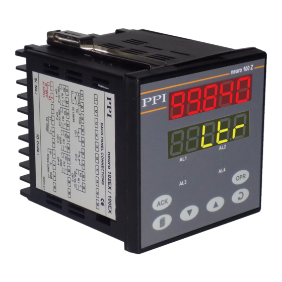
neuro 100 Z User Manual Section 1 FRONT PANEL LAYOUT The indicator front panel comprises of digital readouts, LED indicators and tactile keys as shown in Figure 1.1 below. Figure 1.1 neuro 100 Z Upper Readout Lower Readout Alarm-2 Status Alarm-1 Status Alarm-3 Status Alarm-4 Status... - Page 4 neuro 100 Z User Manual KEYS There are six tactile keys provided on the front panel for configuring the indicator, setting-up the parameter values and selecting Operation / Display Modes. Refer Table 1.2 below. Table 1.2 Symbol Function Press to enter or exit set-up mode. PAGE Press to decrease the parameter value.
-
Page 5: Basic Operation
neuro 100 Z User Manual Section 2 BASIC OPERATION POWER-UP Upon power-up, all displays and indicators are lit on for approximately 3 seconds. This is followed by the indication of the indicator model name on the Upper Readout and the firmware version on the Lower Readout, for approximately 1 second. - Page 6 neuro 100 Z User Manual Table 2.2 Settings Parameter Description (Default Value) ALARM-1 SETPOINT The setpoint for Alarm-1. This parameter is not available if the selected Alarm type for Alarm-1 is ‘None’. ALARM-2 SETPOINT Throughout the range for The setpoint for Alarm-2. This parameter is not available if the the selected Input Type.
-
Page 7: Set-Up Mode Access And Operation
neuro 100 Z User Manual Section 3 SET-UP MODE : ACCESS AND OPERATION The various parameters are arranged in different groups, called PAGES, depending upon the functions they represent. Each group is assigned a unique numeric value, called PAGE NUMBER, for its access. The parameters are always presented in a fixed format: The Lower Readout displays the parameter prompt (Identification Name) and the Upper Readout displays the set value. - Page 8 neuro 100 Z User Manual Notes 1. Each page contains a fixed list of parameters that are presented in a pre-determined sequence. Note however that availability of a few parameters, called Conditional Parameters, depend upon the settings for some other parameters. For example, the parameter ‘Alarm Setpoint’...
-
Page 9: Alarm Parameters
neuro 100 Z User Manual Section 4 ALARM PARAMETERS Visit www.ppiindia.net for technical notes on ALARM for detailed understanding of the parameters / terminologies used for describing the Alarm parameters in this section. The parameters required for configuring Alarms are grouped on PAGE-10. The configuration includes selecting the type of Alarm, setting the hysteresis value, enabling / disabling start-up Alarm suppression, etc. - Page 10 neuro 100 Z User Manual Settings Parameter Description (Default Value) ALARM LOGIC Normal Select ‘Normal’ if Alarm is to activate an Audio / Visual alarm. Reverse Select ‘Reverse’ if Alarm is to Trip the system. (Default : Normal) ALARM LATCH The Relay switches ON/OFF with Alarm switching.
-
Page 11: Retransmission Parameters
neuro 100 Z User Manual Section 5 RETRANSMISSION PARAMETERS The parameters required for configuring Retransmission are grouped on PAGE-11. The configuration includes selecting the Output type, Recorder Low & High settings etc. Refer Table 5.1 for parameter description & settings. Note that the Parameters on this page are presented only if Retransmission feature is enabled on Supervisory Level. -
Page 12: Input Configuration
neuro 100 Z User Manual Section 6 INPUT CONFIGURATION PARAMETERS The indicator needs to be appropriately configured for Sensor/Transmitter Input type, PV indication, digital filter etc. The PAGE-12 parameters are listed below in Table 6.1. Table 6.1 Settings Parameter Description (Default Value) INPUT TYPE Refer Table 6.3... - Page 13 neuro 100 Z User Manual Table-6.2 Lower Readout Units °C °F Kelvin Engineering Units Percentage Pascals Mpascals Kpascals Milli bar kg/sq cm mm water gauge Inches water gauge mm mercury Torr Liters per hour Liters per minute % Relative Humidity % O2 % Co2 % Carbon Potential...
- Page 14 neuro 100 Z User Manual Lower Readout Units Minutes Hours Miles per hour Milli grams Grams Kilo grams Table 6.3 Range (Min. to Max.) Option What it means Resolution 0 to 20mA DC current 4 to 20mA DC current 0 to 50mV DC voltage 0 to 200mV DC voltage -19999 to +99999 units 0.01...
-
Page 15: Supervisory Parameters
neuro 100 Z User Manual Section 7 SUPERVISORY PARAMETERS The supervisory level responsibilities include exercising control over operator, making process related decisions and controlling the availability of process data for remote use. The PAGE-13 parameters allow implementation of supervisory level decisions. -
Page 16: Hardware Assembly & Configurations
neuro 100 Z User Manual Section 8 HARDWARE ASSEMBLY AND CONFIGURATIONS The Figure 8.1 below shows the indicator outer-case viewed with front label upright. Figure 8.1 Ventilations Panel Mounting Clamp Bezel Rear Terminals Enclosure Front Label Pullout Latch Connection Diagram ELECTRONIC ASSEMBLY The basic electronics assembly (without any plug-in modules), comprises of 4 Printed Circuit Boards (PCB). - Page 17 neuro 100 Z User Manual Figure 8.2 Latching Slot PulloutLatch Removing Assembly from Enclosure Hold the indicator upside down and press the pullout latch to unlock the front bezel from the enclosure (Refer Figure 8.2 above). Pull the bezel outward. The electronics assembly comes out with the bezel. Placing Assembly Back into Enclosure Hold the Enclosure and the Bezel such that the Latching Slot on the Enclosure and the Pullout Latch on the Bezel face upward (See Figure 8.2).
- Page 18 neuro 100 Z User Manual Figure 8.3 Shorting Pins Link CPU PCB Input Jumper Settings Output PCB Output-1 Jumper Settings Output-1 Jumper Settings INPUT : Jumper Settings In addition to parameter settings, the Input Type selection also requires proper jumper settings. For the jumper settings; Pins & Shorting-Link arrangement, marked ‘A’, is provided on the CPU PCB as shown in Figure 8.3.
- Page 19 neuro 100 Z User Manual Table 8.1 Output-1 Jumper Settings Output Type Jumper Setting - B Jumper Setting - C Relay SSR Drive OUTPUT PLUG-IN MODULES (OP2, OP3, OP4 & OP5) The indicator supports 3 types of ‘Plug-in Modules’ that can be used as outputs (OP2, OP3, OP4 & OP5).The 3 types are; (a) Relay /SSR Module, (b) DC Linear Voltage Module and (c)DC Linear Current Module.
- Page 20 neuro 100 Z User Manual Figure 8.5(b) Mounting Parts for Output Modules 5-Pin Male Plug 4-Pin Male Plug 5-Pin Male Plug CPU PCB Output PCB 4-Pin Male Plug Figure 8.6 Power-Supply CPU PCB Output PCB...
- Page 21 neuro 100 Z User Manual The Figure 8.5(a) shows the 4 & 5 Pin Female Sockets mounted on the bottom side of the output modules. The Figure 8.5(b) shows the 4 & 5 Pin Male Plugs Mounted on the CPU & Output PCBs. For clarity, the modules and the Power-Supply PCB are not shown in the figure.
- Page 22 neuro 100 Z User Manual (b) DC Linear Voltage Module (c) DC Linear Current Module The DC Linear Module, shown in Figure 8.8 below, is factory configured for either Current or Voltage output and is supported by OP5 only. The DC Current Module can be configured to output either 0-20 mA or 4-20 mA by appropriate parameter settings.
-
Page 23: Mechanical Installation
neuro 100 Z User Manual Section 9 MECHANICAL INSTALLATION The following precautions should be strictly observed while installing the indicator: 1. The place of installation should be free of corrosive / combustible gases and electrically conductive pollution. 2. Ensure that the place of installation is not subject to rapid ambient changes that can cause condensation. Also the Ambient Temperature and Relative Humidity surrounding the indicator should not exceed the maximum specified for the proper operation of the indicator. - Page 24 neuro 100 Z User Manual Figure 9.2 Panel Cutout 92 X 92 mm -0, +0.5 mm (3.62 X 3.62 in) (-0, +0.02 in) 10mm (0.39in) Figure 9.3 Panel Mounting Clamp Tighten the screw Mounting Panel with Square Cutout Metallic Projection...
-
Page 25: Electrical Connections
6. Make sure that the indicator supply is switched-off while making/removing any connections or removing the indicator from its enclosure. CONNECTION DIAGRAM The rear panel electrical wiring connection diagram is shown in Figure10.1 below. Figure 10.1 neuro 100Z BACK PANEL CONNECTIONS Pt100 DI-1 DI-2... - Page 26 neuro 100 Z User Manual The Electrical Connection Diagram is shown on the left side of the indicator enclosure. The diagram shows the terminals viewed from the REAR SIDE with the indicator label upright. The Connection Diagram is a generic one; the connections shown for optional modules are applicable only if the modules are fitted.
- Page 27 neuro 100 Z User Manual POWER SUPPLY (Terminals 1 & 2) Figure 10.4 2 Pole Power Supply Isolating Switch Terminal Fuse Line 1 (L) 2 (N) Neutral The indicator is designed for installation in an enclosure which provides adequate protection against electric shock.
- Page 28 neuro 100 Z User Manual If the Optional plug-in communication board is fitted, connect terminal 7 and 8 of the indicator to (+) and (-) terminals of the Master device. For reliable noise free communication, use a pair of twisted wires inside screened cable as shown in Figure 10.5. The wire should have less than 100 ohms / km nominal DC resistance (Typically 24 AWG or thicker).
- Page 29 Process Precision Instruments 101, Diamond Industrial Estate, Navghar, Vasai Road (E), Dist. Palghar - 401 210.Maharashtra, India Sales : 8208199048 / 8208141446 Support : 07498799226 / 08767395333 sales@ppiindia.net, support@ppiindia.net w w w . p p i i n d i a . n e t...
Need help?
Do you have a question about the neuro 100Z and is the answer not in the manual?
Questions and answers