
Subscribe to Our Youtube Channel
Related Manuals for Fass FA D10 125G


Summary of Contents for Fass FA D10 125G
- Page 1 INSTALLATION MANUAL APPLICATION: FA D10 125G (125gph @ 45psi) Cummins 5.9L 12 Valve *with P7100 Injection pump* **bypassing the factory lift pump** 1994-1998...
- Page 2 Building extremely “High-Quality” fuel products is our business. We concentrate all of our efforts in this arena. No one else is as specialized as FASS in what we do! This is one of the ingre- dients to insure you are running with the “Highest-Quality” fuel system in the world! We have im- plemented very rigorous testing procedures to provide the “Highest Quality”...
- Page 3 Flush and clean all brass fittings and fuel line from debris. Keep debris from entering the internals of the system during installation. Getting debris in the “T” port can lock up the motor. If the motor does lock up from debris call FASS for technical assistance.
- Page 4 4. For best results in accuracy and efficiency (due to training, communication, and our relationship with our dealer network), we recommend an Authorized or ViP FASS Fuel Systems dealer for the installation. They are prepared to install the FASS fuel pumps with the most efficiency. If a situation/problem arises during the installation, they are the most prepared for that situation/problem.
-
Page 5: Installation
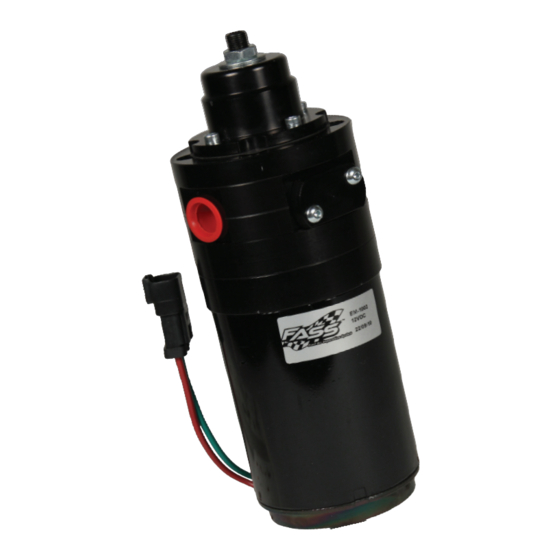
Adjustable Fuel Pump Series 125 GPH 45 PSI (Approximately) A fuel pressure gauge is highly recommended to identify fuel filter life and to prevent engine damage! Adjustment Lock Nut Set screw Boost Compensation Port ‘T’ Fuel Inlet Port “E” To Engine Fuel Pressure Port Installation Step 1:... - Page 6 Contents THB-1001 BHB-1001 FF-3270 MP-9036 *Cable Ties* WH-1005 FL-1001 x14’...
-
Page 7: Mounting Template
Mounting Package Contents WE-1001 RS-1002 NP-1001 PL-1003 10-300 DIPF-1001 PL-1002 1/4” Nut 1/4 - 20x3.5” Ring Terminal 1/4” Lock Washer QD-1001 4 1/4 - 20x1.75” Fuse Tap Flag Terminal HC-1001 Mounting template... - Page 8 The installation of the electrical harness is done first, allowing power to be applied to the pump for lubrication purposes later in the installation. a. Disconnect battery before beginning installation. Attach WE-1001 to the WH-1005 Wiring Harness. Route WE-1001 red lead through the fire wall Fuse b.
- Page 9 FASS pump. Reconnect the battery. Turn key to the “On” position. With the FASS pump on, squirt a liberal amount of WD-40 or other lubri- cant into the “T” port. This procedure will “wet” the Gerotor and allow for better suction during initial priming.
- Page 10 Loop fuel line over frame. This will be addressed in step Installing Fuel Line. Plug or seal factory line or remove. c. Route fuel line to the suction port on the FASS pump labeled “T”. Cut the fuel line. Insert PL-1002 into fuel line using oil. Attach to 10-300 in ‘T’...
- Page 11 f. Disconnect factory fuel line and injector return line from inlet side of the factory fuel filter and install the DIPF-1001. Torque to 18 ft./lbs. g. Measure and cut fuel line. Insert PL-1003 90° Push-Lok fitting using oil. Attach the PL-1003 to DIPF-1001. Torque to 18 ft./lbs. i.
- Page 12 Electrical harness and fuel lines secured and properly tightened? Has the system been primed? 1. Turn key to the ignition position, turning on the FASS pump for 15 sec.. 2. Crank engine and allow to run for at least 1 minute.
- Page 13 Disclaimer: To help insure you receive the proper system and customer support at the local level, FASS has a VIP and Authorized Dealer network representing FASS products. This is one reason you must purchase through a dealer to comply with our warranty policies.
Need help?
Do you have a question about the FA D10 125G and is the answer not in the manual?
Questions and answers