Table of Contents
Advertisement
Quick Links
INSTRUCTION MANUAL
NPPA-TT-SD50
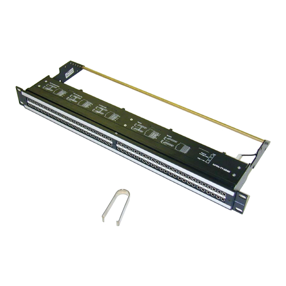
PATCH PANEL "Easy Patch"
D-subminiature
NEUTRIK AG
NEUTRIK Zürich AG
Liechtenstein
Switzerland
Tel.: +423/237 24 24 Tel.: +41 44/736 5010
Fax: +423/232 53 93 Fax: +41 44/736 5011
www.neutrik.com
Draft. Nr.:
BDA82-0
16.01.2009
Update:
Data subject to change without prior notice. ©2007 NEUTRIK . ALL RIGHTS RESERVED.
NEUTRIK (UK) Ltd.
NEUTRIK USA INC.
Great Britain
USA
Tel.: +44 1983/811 441 Tel.: +1 732/901 9488
Fax: +44 1983/811 439 Fax: +1 732/901 9608
|
96 Bantam (TT) Jacks, 50 pin
NEUTRIK Tokyo Ltd.
NEUTRIK France
Japan
France
Tel.: +81 3/3663 4733
Tel.: +33 1/4131 6750 Tel.: +49 8131/28 08 90
Fax: +81 3/3663 4796
Fax: +33 1/4131 0511 Fax: +49 8131/28 08-30
NEUTRIK Vertriebs GmbH
Germany/Netherlands/Austria
Advertisement
Table of Contents

Related Manuals for NEUTRIK NPPA-TT-SD50


Summary of Contents for NEUTRIK NPPA-TT-SD50
- Page 1 Fax: +423/232 53 93 Fax: +41 44/736 5011 Fax: +44 1983/811 439 Fax: +1 732/901 9608 Fax: +81 3/3663 4796 Fax: +33 1/4131 0511 Fax: +49 8131/28 08-30 www.neutrik.com Draft. Nr.: BDA82-0 16.01.2009 Update: Data subject to change without prior notice. ©2007 NEUTRIK . ALL RIGHTS RESERVED.
-
Page 2: Table Of Contents
NPPA-TT-SD50 Instruction Manual Index 1. Electrical configuration....................3 2. Replacement of Jack Pairs ..................4 3. Reconfiguration by hand....................5 4. Grounding variations ....................7 5. Wiring ..........................9 6. Cable retention to the unit..................10 7. Channel identification ....................10 8. Technical data ......................12 9. Wiring Diagram......................13 10. -
Page 3: Electrical Configuration
NPPA-TT-SD50 Instruction Manual 1. Electrical configuration The Neutrik ”Easy Patch” is fitted with high quality, long life NJ3TTA double contact jacks (2 x 48) with drastically improved contact integrity. The NJ3TTA double contact jacks are gold plated and prewired. The Neutrik ”Easy Patch” is an innovative and compact patching system (just 1 U high) for 19”... -
Page 4: Replacement Of Jack Pairs
NPPA-TT-SD50 Instruction Manual 2. Replacement of Jack Pairs Each individual jack pair can be exchanged or re-configured without fuss even while the unit is “on air”. For replacement or re-configuration just remove the easy accessible module consisting of two “Plug-in Units”. -
Page 5: Reconfiguration By Hand
NPPA-TT-SD50 Instruction Manual Alternatively the jack pairs may be pulled out by the use of two Bantam plugs (diagonally plugged in). The two jack pairs have to be re-assembled in the right way so that the thicker body marked “left” is put on the left side with the mark outside and readable. - Page 6 NPPA-TT-SD50 Instruction Manual ...to slide the jack pairs against each other in axial direction. Then remove the cover with a tiny grip at the side and carefully Pull out the configuration bars you need to exchange (preferably using a small screw-driver).
-
Page 7: Grounding Variations
NPPA-TT-SD50 Instruction Manual 4. Grounding variations The patch panel is terminated with 4 Sub-D connectors each of them corresponding to groups (Sub-D groups) of 12 channels. Each Sub–D connector has only two ground contacts: • one for the top row connecting all top row ground contacts •... - Page 8 NPPA-TT-SD50 Instruction Manual Jumper Setting Floating Grounding Variations Note: Phantom powered microphones In general it is not recommended to run phantom power through patch panels. In the case it is required to patch phantom powered microphones, all of the shields (SLEEVE contacts) from this device must be tied together.
-
Page 9: Wiring
NPPA-TT-SD50 Instruction Manual 5. Wiring Four Sub-D connectors with 50 pins each enable fast and easy wiring even with the patch panel installed in the rack. Rear front for wiring 50 pin Sub-D connector terminal (SD50) Pin Header Page 9 of 14... -
Page 10: Cable Retention To The Unit
NPPA-TT-SD50 Instruction Manual 6. Cable retention to the unit The built in cable retention bar is at the back of the casing. Simply attach the cables with cable ties to the bar. For large and heavy bundles there is an additional strain relief bar NPPA-S available. It is attached to the casing with four screws. - Page 11 NPPA-TT-SD50 Instruction Manual For the perfect management of the system and for individual identification according to customer’s needs there are two large and separate labeling strips, one for the bottom and one for the top row. To write on the paper you have to unscrew one of the outer fixing screws of the front panel.
-
Page 12: Technical Data
NPPA-TT-SD50 Instruction Manual 8. Technical data 8.1 Electrical Frequency range: DC to > 50 MHz Digital suitability: Digital audio acc. to AES/EBU > 100 dB @ 10 kHz, 600 Ω terminated Channel separation: > 40 dB @ 6 MHz, 110 Ω terminated Insulation resistance: >... -
Page 13: Wiring Diagram
NPPA-TT-SD50 Instruction Manual 9. Wiring Diagram Page 13 of 14... -
Page 14: Ordering Information
NPPA-TT-SD50 Instruction Manual Ordering Information 10.1 Standard supply The compact Neutrik "Easy Patch” NPPA-TT-SD50 consists of: • B lack coated steel casing with aluminum fittings • 2 x 48 highly integrated NJ3TTA jacks with gold plated double contacts and specially designed normalling mechanism (standard: half normalled bottom row) •...
Need help?
Do you have a question about the NPPA-TT-SD50 and is the answer not in the manual?
Questions and answers