
Related Manuals for Impecca IWAH25-KRB


Summary of Contents for Impecca IWAH25-KRB
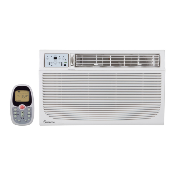
- Page 1 Window Air Conditioner with Heat —User's Guide Model: IWAH25-KRB (25,000 BTU Cooling, 16,000 BTU Heating, 230/208V) www.impecca.com v0.3...
- Page 2 6 horas y un tiempo recomendado de 24 horas antes de encender la primera vez. Spanish version of this manual available for download on www.impecca.com Read the following notices and information carefully to ensure proper operation of your air conditioner unit.
-
Page 3: Table Of Contents
TABLE OF CONTENTS Introduction ..........................6 Getting To Know Your Air Conditioner ..................7 Using Your Air Conditioner .....................8 Delay Start/Stop (Timer) ...................... 11 Additional Features and Information ................12 Pre-installation Instructions....................13 Window Installation ......................16 Through-The-Wall Installation .................... 23 Masonry Construction ......................26 Cleaning &... - Page 4 READ THESE NOTICES CAREFULLY—THEY ARE IMPORTANT! WARNING Do not start or stop the unit by inserting or Do not damage power cord or replace Plug in power plug completely. pulling out the power plug. with a non-original power cord. •...
- Page 5 CAUTION Stop operation and remove unit from Hold the plug by the head of the power Unplug the power cord when not using window in severe storm or hurricane. plug when unplugging unit. the unit for extended periods of time. •...
-
Page 6: Introduction
INTRODUCTION Thank you for purchasing this quality Impecca window air conditioner unit. To ensure the longest life and highest energy efficiency of your unit, please carefully follow these operating instructions. Keep these instructions in a safe place and consult them as needed. -
Page 7: Getting To Know Your Air Conditioner
OPERATING CONDITIONS • The air conditioner must be operated within the temperature range of 62°F to 95°F (16°C to 35°C). • A perimeter of 12′′ (30cm) around the air conditioner should be free of all objects. • Keep air inlet and air outlet clean and free of obstructing objects. •... -
Page 8: Using Your Air Conditioner
USING YOUR AIR CONDITIONER OVERVIEW OF CONTROLS FUNCTIONS Before you begin, thoroughly familiarize yourself with the control panels as shown below and all its functions, then follow the symbol for the functions you desire. The unit can be controlled by the unit control panel located on the front of the device or with the remote controller. - Page 9 TEMPERATURE ADJUSTMENT Press or hold either Down or Up button until the desired temperature is seen on the display. This temperature will be automatically maintained anywhere between 62° F (17° C) and 86° F (30° C). If you want the display to read the actual room tempera- ture, refer to "FAN ONLY MODE"...
- Page 10 PMTS — FOLLOW ME Personal Mapping Temperature Sensor: Your model may be equipped with a special feature that allows the remote control to act as a thermostat. If your unit shows this PMTS LED on the control PMTS panel, and you have the accompanying LCD remote control then your unit is equipped.
-
Page 11: Delay Start/Stop (Timer)
DELAY START/STOP (TIMER) The timer buttons enable two separate functions: one to au- tomatically start the unit within a 24 hour period of time and another to automatically turn off the unit within a 24 hour period of time. These functions are called, respectively, AUTO ON and AUTO OFF. -
Page 12: Additional Features And Information
ADDITIONAL FEATURES AND INFORMATION FRESH AIR VENT When cooling, always leave the vent closed (Fig. A). When operating the unit in fan only mode, you may also open the vent (Fig. B) Another option is opening the vent and exhaust at the same time(Fig. C), which is good for re- moving odors from the room during fan mode. -
Page 13: Pre-Installation Instructions
PRE-INSTALLATION INSTRUCTIONS REQUIRED TOOLS (NOT INCLUDED) 3/32” 1/8” Level Scissors drill bits Pencil Drill Phillips Screwdriver Tape Measure INCLUDED PARTS & ACCESSORIES* 1. Air conditioning unit 10. Right-angle Safety Lock (x1) 2. Flexible window filler panels 11. Foam insert 3. Upper Rail Angle Bracket (x1) 12. - Page 14 UNIT CHASSIS EXPLODED VIEW Window Sash Seal Safety Lock and ¾” (or ½”) length Hex Head Screw Upper Rail Foam Gasket Washer Head Locking Screw Frame Assembly (Le ) Side Retainer Bottom rail ½” length Screw seal Frame and Locknuts Assembly (Right) Locknut...
- Page 15 WINDOW REQUIREMENTS Your air conditioner is designed OFFSET to be installed in standard EXTERIOR double hung windows with WALL minimum width and height requirements as follows: INNER WINDOW SILL : Opening width of 31 inches. : Opening height of 19.5 inch- INTERIOR WALL Wooden Windows...
-
Page 16: Window Installation
WINDOW INSTALLATION Use caution when unpacking and installing. Sharp edges can cause injury. Appearance of unit in these diagrams is for illustrative purposes only and may not precisely reflect your unit’s design. BEFORE YOU BEGIN 1. Check for anything that could block airflow: Any shrubs, trees, awnings on the outside;... - Page 17 bottom left side and repeat on the right side. Gently dislodge, noting that the con- trol panel will be connected to the main unit (Figures C, D). 5. Disconnect the connector plug of the control panel and place the front panel to one side, with the control panel still attached (Fig.
- Page 18 STEP 2: INSTALL UPPER RAIL AND SIDE BRACKETS 1. Affix foam gasket to bottom of upper rail bracket (if not already affixed). 2. Install upper rail and side retainers to cabinet as shown using a total of 10 5/16” screws, with the screws being inserted from the inside of the cabinet.
- Page 19 3. Shift cabinet left or right as needed to line up the center on the line you marked on the window stool. 4. Fasten cabinet to window stool with two screws. (You may wish to drill pilot holes in advance.) Bottom Rail Seal ¾”...
- Page 20 12” Screws and nuts Locknut Right Sill Angle Bracket Mark Flat Head Screw Fig. P Fig. Q 4. Tighten all 6 bolts securely. ½” Screws and Nuts L Fig. R STEP 6: EXTEND WINDOW FILLER PANELS 1. Carefully raise window sash to expose filler panel locking screws. Loosen screws so filler panels slide easily.
- Page 21 through the already extant hole in the middle of the upper rail into the window frame, and drive one ¾” (or ½”) Hex-Head locking screw through hole in the middle of upper rail into the window frame as shown. ¾" (or ½") Hex-Head locking screw I Fig.
- Page 22 2. Attach right-angle safety lock using the ¾” (or ½”) length hex-head screws as shown (Fig. X). Safety Lock ¾" (or ½") Hex-Head locking screw I Fig. X STEP 9: INSTALL CHASSIS INTO CABINET AND REATTACH FRONT PANEL. 1. Lift air conditioner chassis and carefully slide into cabinet leaving 6 inches protrud- ing.
-
Page 23: Through-The-Wall Installation
THROUGH-THE-WALL INSTALLATION Note: Consult local building codes prior to installation, or hire a qualified carpenter. STEP 1: SELECT WALL LOCATION The air conditioner has a slide-out chassis, so that it can be installed through an out- side wall as specified below: •... - Page 24 Y: Inside Frame Height: 18 ⅞" (47.9cm) Inside Frame X: Inside Frame Width: 26¾" (67.9cm) Height Inside Frame Width Up to Fig. AB 8 ½” 4. Build a wooden frame with the inside dimensions of your model as listed above. (Remember to measure twice, cut once!) Frame depth should be the same as the thickness of the wall.
- Page 25 STEP 3: PREPARE AND INSTALL CABINET 1. Slide chassis from cabinet. 2. For detailed instructions, see Step 1, in the Window Mounting section, above. 3. Place cabinet into opening with bottom rail resting firmly on bottom board of wooden frame. 4.
-
Page 26: Masonry Construction
8. Screw or nail cabinet wooden frame using shims if frame is oversized, to eliminate distortion. See diagram. Remember to maintain proper slop as described in Step 3. Fig. AG 9. Re-insert chassis into cabinet by following all steps in Step 8 of Window Mounting. OPTIONAL: Caulking and installation of trim on interior wall may be done. -
Page 27: Cleaning & Maintenance
CLEANING & MAINTENANCE SAFETY WARNING To avoid electric shock, fire, damage, or injury while performing maintenance on your unit: • Always turn off and disconnect the air conditioner from electric power. • Never submerge the unit in water or spray liquids directly on the unit. •... -
Page 28: Troubleshooting
or other harder to remove substances is on the unit, use a wrung-out cloth dampened with warm, soapy water. Use a soft brush to clean off the grille. CLEANING THE FILTER For energy efficient operation, your filter should be cleaned at least once a month. Units in dusty environments may require more frequent filter cleaning. -
Page 29: Electrical Information
trician to troubleshoot and upgrade your electrical circuits if your air conditioner unit exceeds the rated capacity. FOG BLOWS OUT DURING COOLING • In warm, high humidity environments this may naturally occur. Continued cooling will remove excess humidity from the room and the fog will disappear. THE UNIT EMITS A STRANGE SMELL •... -
Page 30: Customer Support
If you wish to contact us by phone, please be sure to have your model number and serial number ready and call us between 9:30am and 5:00pm ET, at +1 866-954-4440. Keep tabs on Impecca’s newest innovations & enter contests via our social network feeds: ... -
Page 31: One-Year Limited Appliance Warranty (Us)
13. Surcharges that may apply to service calls on weekends, from the date of the original purchase, Impecca™, at its nights, holidays. Damages to the finish of appliance or own discretion, will repair or replace the product parts household furnishings due to installation of appliance. -
Page 32: Garantía Limitada Por Un Año (Us)
Para obtener el servicio de garantía de un distribuidor autori- de la casa debido a la instalación del electrodoméstico. zado de Impecca™ envíenos un correo electrónico a: service@ 14. Daños causados por cualquiera de las siguientes causas: impecca.com para obtener un número de Autorización de Actos de Dios, incendios, mal uso. -
Page 33: Garantie Limitée D'un An (Us)
L’usure normale de l’appareil n’est pas couverte par cette Aucun revendeur, agent ou employé d’Impecca™ n’est garantie. Impecca™ se réserve le droit de déterminer le niveau autorisé à effectuer une modification, une extension, un d’usure sur l’ensemble de ses appareils. Ouvrir le boîtier ou changement ou un amendement de cette garantie sans le modifier l’appareil annule dans son entièreté... -
Page 34: Notes
NOTES... -
Page 35: Notes
NOTES... - Page 36 © 2017 Impecca, a division of LT Inc., Wilkes Barre, PA.
Need help?
Do you have a question about the IWAH25-KRB and is the answer not in the manual?
Questions and answers