Table of Contents
Advertisement
Quick Links
Advertisement
Table of Contents

Subscribe to Our Youtube Channel
Related Manuals for PPI neuro 200


Summary of Contents for PPI neuro 200
- Page 1 200 neuro 200 User Manual Advanced Universal Process Indicator User Manual...
-
Page 2: Table Of Contents
200 User Manual CONTENTS FRONT PANEL LAYOUT BASIC OPERATION SET-UP MODE ACCESS AND OPERATION PAGE-10 : ALARM PARAMETERS PAGE-11 : RETRANSMISSION PARAMETERS PAGE-12 : INPUT CONFIGURATION PAGE-13 : SUPERVISORY PARAMETERS PAGE-33 : USER LINEARISATION PARAMETERS MECHANICAL INSTALLATION 10. ELECTRICAL CONNECTIONS... -
Page 3: Front Panel Layout
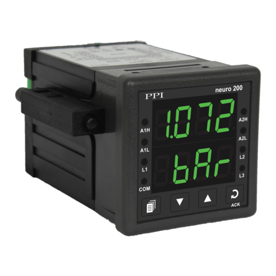
200 User Manual Section 1 FRONT PANEL LAYOUT The indicator front panel comprises of digital readouts, LED indicators and membrane keys as shown in Figure 1.1 below. Figure 1.1 neuro 200 Upper Readout Alarm-1 High / Low Alarm-2 High / Low... - Page 4 200 User Manual KEYS There are four tactile keys provided on the front panel for configuring the indicator, setting-up the parameter values. Refer Table 1.2 below. Table 1.2 Symbol Function PAGE Press to enter or exit set-up mode. Press to decrease the parameter value. Pressing once decreases DOWN the value by one count;...
-
Page 5: Basic Operation
200 User Manual Section 2 BASIC OPERATION POWER-UP Upon power-up the controller executes the following sequence of operations. Checks for Sensor Fault. If the connected sensor type is RTD Pt100 and the selected sensor type is any of thermocouples ·... - Page 6 200 User Manual Accessing Operator Page & Adjusting Parameters Step through the following sequence to open the operator page and to adjust the operator parameter values. 1. Press and release PAGE key. The Lower Readout shows (PAGE) and Upper Readout shows (0).
- Page 7 200 User Manual Settings Parameter Description (Default Value) RESET PASSWORD 0 to 250 For resetting the Min/Max values, set the reset command to ‘Yes’ (Default :0) and then enter the correct password. Min to max Range ALARM-1 SETPOINT specified for the selected Input Type The setpoint for Alarm-1.
-
Page 8: Set-Up Mode Access And Operation
200 User Manual Section 3 SET-UP MODE : ACCESS AND OPERATION The various parameters are arranged in different groups, called PAGES, depending upon the functions they represent. Each group is assigned a unique numeric value, called PAGE NUMBER, for its access. - Page 9 200 User Manual MASTER LOCKING The indicator facilitates locking all the PAGES (except Operator PAGE) by applying Master Lock Code. Under Locking, the parameters are available for view only and cannot be adjusted. The Master Lock, however, does not lock the operator parameters.
-
Page 10: Page-10 : Alarm Parameters
200 User Manual Section 4 PAGE-10 : ALARM PARAMETERS The parameters required for configuring Alarms are grouped on PAGE-10. The configuration includes selecting the type of Alarm, setting the hysteresis value, enabling / disabling start-up Alarm suppression, etc. Refer Table 4.1 for parameter description &... - Page 11 200 User Manual Settings Parameter Description (Default Value) ALARM-2 TYPE None Select the Alarm-2 activation type. Selecting ‘None’ will disable Process Low the alarm and suppress all the related parameters for Alarm-2. Process High (Default : None) Min. to Max. Range...
-
Page 12: Page-11 : Retransmission Parameters
200 User Manual Section 5 PAGE-11 : RETRANSMISSION PARAMETERS The parameters required for configuring Retransmission are grouped on PAGE-11. The configuration includes selecting the Output type, Recorder Low & High settings etc. Refer Table 5.1 for parameter description & settings. -
Page 13: Page-12 : Input Configuration
200 User Manual Section 6 PAGE-12 : INPUT CONFIGURATION PARAMETERS The indicator is needs to be appropriately configured in terms of input and other features like digital filter etc. The PAGE-12 presents Input configuration parameters that are listed below in Table 6.1 . - Page 14 200 User Manual Settings Parameter Description (Default Value) DC RANGE LOW -1999 to 9999 This parameter is available only if the selected input type is DC (Default : 0.0) Voltage / Current and defines the process value corresponding to the Signal Low value from the transmitter.
- Page 15 200 User Manual Table-6.2 Lower Readout Units °C Temperature °F Kelvin Engineering Units Percentage Pascals Mpascals Kpascals Milli bar Pressure kg/sq cm mm water gauge Inches water gauge mm mercury Torr Litres per hour Flow Litres per minute % Relative Humidity...
- Page 16 200 User Manual Lower Readout Units volts Amps Milli amps Electricity Milli Volts Ohms Parts per million Revolutions per pinute Milli seconds Seconds Time Minutes Hours Miles per hour Milli grams Weight Grams Kilo grams mm (Millimeter) cm (Centimeter)
- Page 17 200 User Manual Table 6.3 Option Range (Min. to Max.) What it means Resolution Type J Thermocouple 0 to +960°C / +32 to +1760°F Type K Thermocouple -200 to +1376°C / -328 to +2508°F Type T Thermocouple -200 to +385°C / -328 to +725°F Type R Thermocouple 0 to +1770°C / +32 to +3218°F...
-
Page 18: Page-13 : Supervisory Parameters
200 User Manual Section 7 PAGE-13 : SUPERVISORY PARAMETERS The supervisory level responsibilities include exercising control over operator, making process related decisions and controlling the availability of process data for remote use. The PAGE-13 parameters allow implementation of supervisory level decisions. -
Page 19: Page-33 : User Linearisation Parameters
200 User Manual Section 8 PAGE-33 : USER LINEARISATION PARAMETERS The parameters listed on this PAGE-33 are used to implement the linearisation curve on the process value represented by the DC linear output of a transmitter. The parameters affect the measured PV only if the ‘User Linearisation’ feature is ‘Enabled’... -
Page 20: Mechanical Installation
200 User Manual Section 9 MECHANICAL INSTALLATION OUTER DIMENSIONS AND PANEL CUTOUT The Figure 9.1 shows the controller outer dimensions. Figure 9.1 48mm 94mm (1.89in) (3.70in) neuro 200 7mm (0.276in) Front View Side View PANEL CUTOUT The Figure 9.2 shows the panel cutout requirements for a single controller. - Page 21 200 User Manual PANEL MOUNTING Follow the steps below for mounting the controller on panel: 1. Prepare a square cutout to the size shown in Figure 9.2. 2. Remove the Panel Mounting Clamp from the controller Enclosure and insert the rear of the controller housing through the panel cutout from the front of the mounting panel.
-
Page 22: Electrical Connections
200 User Manual Section 10 ELECTRICAL CONNECTIONS WARNING WARNING MISHANDLING / NEGLIGENCE CAN RESULT IN MISHANDLING / NEGLIGENCE CAN PERSONAL DEATH OR SERIOUS INJURY. RESULT IN PERSONAL DEATH OR SERIOUS INJURY. 1. The user must rigidly observe the Local Electrical Regulations. - Page 23 200 User Manual DESCRIPTIONS The back panel connections are described as under: PV INPUT : RTD Pt100, 3-wire / Thermocouple / mA / mV / V (Terminals : 17, 16, 15) Figure 10.2 (a) Figure 10.2 (b) Figure 10.2 (c)
- Page 24 200 User Manual mA / V Output The Positive (+) of mA / V is available at Terminal 14 & the Negative (-) at Terminal 13. Relay Output Potential-free Relay changeover contacts NO (Normally Open) and C (Common) rated 10A/240 VAC (resistive load).
- Page 25 200 User Manual 85~264 VAC : Power Supply (Terminals 1, 2) The controller is supplied with power connections suited for 85 to 264 VAC line supply. Use well-insulated copper conductor wire of the size not smaller than 0.5mm for power supply connections. Connect Line (Phase) supply line to terminal 1 and the Neutral (Return) supply line to terminal 2 as shown in Figure 10.5 below.
-
Page 26: Appendix-A : Dc Linear Signal Interface
(mV/V/mA) and Range. Most PPI instruments, thus, provide programmable Signal Type and Range to facilitate interface with a variety of transmitters. A few industry standard signal types and ranges offered by the PPI instruments are: 0-50mV, 0- 200mV, 0-5 V, 1-5 V, 0-10V, 0-20 mA, 4-20 mA, etc. - Page 27 200 User Manual The following examples illustrate appropriate parameter value selections. Example 1: Pressure Transmitter producing 4 to 20 mA 0 to 5 psi Y (psi) Presume the pressure is to be measured Range High 5.00 with 0.01 Resolution, that is 0.00 to 5.00 psi.
- Page 28 200 User Manual Process Precision Instruments 101, Diamond Industrial Estate, Navghar, Vasai Road (E), Dist. Palghar - 401 210.Maharashtra, India Sales : 8208199048 / 8208141446 Support : 07498799226 / 08767395333 sales@ppiindia.net, support@ppiindia.net w w w . p p i i n d i a . n e t...
Need help?
Do you have a question about the neuro 200 and is the answer not in the manual?
Questions and answers