
Subscribe to Our Youtube Channel
Related Manuals for Broce BB250


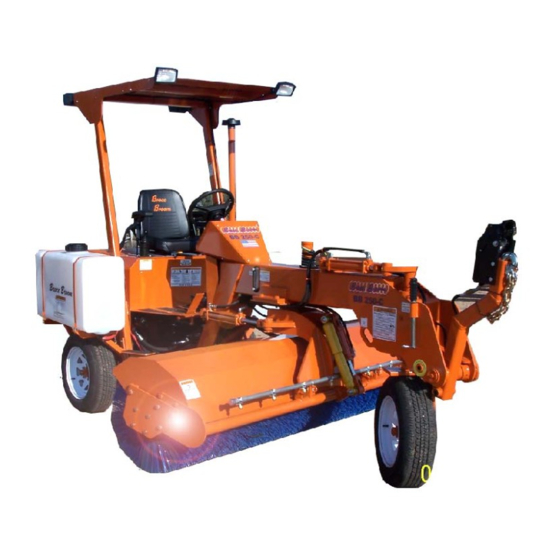
Summary of Contents for Broce BB250
- Page 1 Table of Contents Serial Numbers 301001-304262 BB250 Self Propelled Multi Purpose Sweeper SERVICE -MAINTENANCE & PARTS MANUAL BROCE MANUFACTURING CO 1460 South Second Ave Dodge City, Ks 67801 Tele 620-227-8811 Fax 620-227-3012 1:25 pm, Aug 05, 2020...
- Page 2 If this Document is not signed and returned to Broce Manufacturing Co. Inc., the warranty begins at the date of delivery to the Dealership.
- Page 3 For a period of twelve (12) months or 1,000 hours whichever comes first, from the date of delivery of product to the original user, Broce Manufacturing of Dodge City, Kansas warrants each product to be free from manufacturing defects, subject to the limitations contained in this policy.
- Page 4 Table of Contents TABLE OF CONTENTS DESCRIPTION PAGE # WARRANTY SPECIFICATIONS STANDARD AND OPTIONAL EQUIPMENT START UP AND PROPELLING TOWING PROCEDURES OPERATION OF THE SWEEPING CORE SWEEPING TIPS EXTENDING BRUSH LIFE MACHINE OPERATION AND SAFETY MACHINE CONTROL LOCATIONS MACHINE SERVICE AND SAFETY GUIDELINES LUBRICATION AND MAINTENANCE BRAKE INSPECTION AND SERVICE ENGINE...
- Page 5 Table of Contents...
- Page 6 Table of Contents MODEL BB-250 Specification Sheet Engine Horse Power 37 H.P. Machine Weight 3,000 LB 3,600 LB w/Water System Broom Size 6 3/8” ID X 24” OD Broom Length Full 8 FT Broom Drive Hydraulic Motor Broom Angle Full 40° (both ways) Steering 60°...
- Page 7 Table of Contents STANDARD EQUIPMENT ON ALL UNITS SAFETY ORANGE PAINT 8’ STEEL CORE W/6 3/8” X 24” POLY CONVOLUTED WAFERS CERTIFIED ROLL-OVER PROTECTION STRUCTURE & CANOPY SEAT BELTS & REVERSE ALARM POWER STEERING 2-WHEEL HYDRAULIC DRUM BRAKES W/MANUAL PARKING BRAKE 37 H.P.
- Page 8 Table of Contents START UP & PROPELLING CAUTION: OPERATOR MUST BE SEATED WITH SEAT BELT PROPERLY SECURED WHILE ENGINE IS RUNNING. This model of broom is hydrostatically driven. Motion is achieved by depressing the foot pedal on the floor board to the right of center. Letting the foot pedal up will result in a braking action caused by the hydraulic system.
- Page 9 The speed at which this machine is towed depends on road conditions and the personal judgement of the individual in charge. Broce Manufacturing Co. will not be responsible for neglect or poor judgement at anytime during machine operation and/or towing of the machine.
- Page 10 Table of Contents OPERATION OF THE SWEEPING CORE All functions of the sweeping core are hydraulically operated. Two control valve handles are mounted to the right of the operator’s seat for controlling these functions. The Joystick controls the core height up down and the right and left angle of Broom.
- Page 11 Table of Contents SWEEPING TIPS If the broom starts to hop or bounce, the propelling speed is too high. Slow the machine down, but maintain high engine speed. This will allow you to do a good job on the first pass and you will not need to go over it again.
- Page 12 More down pressure does not give a result of better sweeping. The broom gets its sweeping action by the flicking action of the bristles. Broce Brooms are equipped with a float detent control valve. This function should be used as often as possible for optimum sweeping and longer brush life.
- Page 13 Table of Contents MACHINE 0PERATION AND SAFETY GUIDELINES Read all decals and manuals before starting and/or operation this machine. Do not operate or make any adjustments or repairs to the machine if parking brake will not hold machine from rolling. If the parking brake will not keep the machine from rolling adjust, repair or replace it before operating, adjusting or repairing the machine.
- Page 14 Table of Contents MACHINE 0PERATION AND SAFETY GUIDELINES 15. Do not start, service, operate or make any adjustments to this machine before you have read and fully understood all of this manual. 16. Familiarize yourself with all operation and safety decals before operating this machine. OPERATIONAL AND SAFETY DECALS WARNING USE PROTECTIVE...
- Page 15 Table of Contents OPERATIONAL AND SAFETY DECALS WARNING DANGER STAND CLEAR WHEN IN USE ! FLYING OBJECTS ! WARNING WARNING HYDRAULIC OIL WARNING STAND CLEAR ! PINCH POINT !
- Page 16 Table of Contents OPERATIONAL AND SAFETY DECALS WARNING CAUTION...
- Page 17 Table of Contents MACHINE OPERATION CONTROLS LOCATION ITEM LOCATION FUNCTION 1. Seat Belt Left and right side of seat. To prevent operator from falling off machine. 2. Parking/Emergency Brake Left of seat and back. To hold machine from rolling when parked and in neutral. To be used for energency stopping of machine.
- Page 18 Table of Contents MACHINE OPERATION CONTROLS LOCATION ITEM LOCATION FUNCTION 7. Broom Left to Right Angle Joystick Control When pulled left, right end of Control broom moves toward front, Float-Down Pressure when pushed right, right end of broom moves back. Left Right Raise...
- Page 19 Table of Contents MACHINE SERVICE AND SAFETY GUIDELINES Read all decals and manuals before starting and operating this machine. Do not operate or make any adjustments or repairs if the Parking Brake does not hold machine. Repair the Parking Brake first, before making any other repairs or adjustments to this machine. Always set Parking Brake before starting and after stopping engine on this machine.
- Page 20 Table of Contents...
- Page 21 Table of Contents...
- Page 22 Table of Contents LUBRICATION AND MAINTENANCE 1. Grease two steering shaft bearings at the front of the machine every day. The front wheel bearings should be cleaned and packed every six months. 3. The tires on the front and rear of the machine should be kept at 32 psi and should be checked on a daily basis.
- Page 23 Table of Contents BRAKE INSPECTION AND SERVICE This machine is equipped with dynamic hydraulic braking, conventional hydraulic brakes and a mechanical Parking Brake. The dynamic hydraulic braking will be in operation any time that the engine is running. When the foot pedal is released, the hydraulic system provides enough braking action that the conventional foot pedal brake should not have to be used.
- Page 24 Table of Contents ENGINE The normal engine operation and maintenance procedures are covered in a separate manual, which is furnished by the engine manufacturer. We do suggest, however, due to the dusty conditions in which these machines operate, that engine fan inspection and replacement should be accomplished more frequently than the engine manufacturer may suggest.
- Page 25 Table of Contents REPAIR PARTS BB250 Self Propelled Multi Purpose Sweeper IMPORTANT! BEFORE ORDERING PARTS PLEASE PROVIDE COMPLETE MODEL AND SERIAL NUMBER WHEN ORDERING PARTS. THIS WILL MAKE FILLING YOUR ORDER EASIER, FASTER AND WILL HELP AVOID ANY UNNECESSARY DELAYS IN PROCESSING YOUR ORDER.
- Page 26 Table of Contents FRAME & ASSOCIATED PARTS Ref # Part # Description 850131 Hood (Kubota Engine) Hood (Caterpillar Engine) 850611 Main Frame 850126 Hydraulic Hose Shield 202358 Dash Cover 202403 Wheel 14”, 5 Bolt 304058 Grease Cap 344124 Outer Bearing Cone 344125 Outer Bearing Cup 344126...
- Page 27 Table of Contents BROOM CORE PARTS Ref # Part # Description 850132 Core Hanger 850137 Core Support Frame 502526 Core Frame End Plate 850139 Core Motor Mount - Left Side 850136 Broom Core RW-503B Single Poly Wafer W/Spacer 344145 Single Wire Wafer W/Spacer 344137 Set - Poly Wafers W/Spacer 344148...
- Page 28 Table of Contents...
- Page 29 Table of Contents HYDRAULIC COMPONENTS...
- Page 30 Table of Contents HYDRAULIC COMPONENTS Ref # Part # Description 305973 Variable Pump w/A-pad 355000 Gear Pump (Danfoss) 305905 Hyd. Motor, Core Drive 305904 Wheel Drive Hyd. Motor 305903 Steering Unit (Danfoss) 344082 Hyd. Filter Head 344150 Hydraulic Filter , 10 Micron 852251 Filter H.P.
- Page 31 Table of Contents Ref. Part # Desription 305901 Complete Valve Assy. 305053 Detent 305058 Handle 305052 Relief Cartrage...
- Page 32 Table of Contents 305900 Valve Assembly Part no. Description 1. 305900 Complete Valve Assy. 2. 305928 Float Detent 3. 305927 Spring Center Detent 4. 305959 Joystick Kit 5. 305960 Load Check ( not shown ) 6. 305962 Seal Kit ( not shown ) 7.
- Page 33 Table of Contents BRAKE PARTS Ref # Part # Description 850153 Brake Pad B-241-R Rubber Brake Pad 850128 Brake Pedal B-242-R Pivot Bushing B-27084A Clevis 3/8” x 3” NF 202304 Brake Actuator Push Rod 344167 Master Cylinder 344220 Master Cylinder Repair Kit 202444 Brake Cylinder Rod Plate, Left Side 202443...
- Page 34 Table of Contents BRAKE PARTS Ref # Part # Description 344179 Parking Brake Lever 344180 Parking Brake Cable 70” 344181 Parking Brake Cable 40” B-27084A Clevis 3/8” x 3” NF 344192 Spanner Nut 344193 Lock Washer 344194 Brake Drum 344189 Brake Assy.
- Page 35 Table of Contents DRIVE HUB COMPONENTS Ref # Part # Description 344199 Snap Ring I.D. 344200 Coupler Sleeve 344192 Spanner Nut 344193 Lock Washer 344201 Tongued Washer 344202 Bearing Cone, Inner 344203 Bearing Cup, Inner 344204 Drive Hub Housing 344205 Brake Lever 344206 Bearing Cup, outer...
- Page 36 Table of Contents ACCELERATOR PEDAL & LINKAGE Ref # Part # Description HC-228-B Boot HC-228-HB Hydro-Back Centering Device HC-228-E Hydro-Back Cable 309453 Cable End 2461 Pivot Bushing 850146 Foot Pedal 400357 5/8 x 11 x 7” (Bolt Only) 400052 5/8 Nylon Nut...
- Page 37 Table of Contents ENGINE EXTERNAL PARTS...
- Page 38 Table of Contents ENGINE EXTERNAL PARTS Ref # Part # Description 344222 Intake Manifold 344223 Speed Control Lever 344224 Engine Stop Lever 344225 Injection Pump 344227 Cooling Fan 344228 Fan Drive Pulley 344229 Oil Filter Cartridge 344230 Oil Filler Plug 344231 Exhaust Manifold 344232...
- Page 39 Table of Contents ENGINE RELATED PARTS Ref # Part # Description 344093 Precleaner Inlet Pipe 850148 Precleaner Inlet Pipe Clamp B9NN9A660A Precleaner Complete B9NN9A663A Precleaner Bowl Only 344107 Rubber Isolator (Kubota & Cat) 202497 Kubota R.H. Motor Mount 202498 Kubota L.H. Motor Mount 850154 Tail Pipe Bracket 850127...
- Page 40 Table of Contents GAUGES, SWITCHES & LIGHTS QUARTZ FUEL HOURS 000006 Ref # Part # Description PBS-13 Parking Brake Switch 344255 Reverse Alarm Switch PBL-12 Warning Light 307044 Key Switch Kubota & Cat 23836 Push Pull Switch RH-250 Reverse Alarm I-222-HO Hour Meter I-223-R...
- Page 41 Table of Contents OPTIONAL WATER SPRAY SYSTEM Ref # Part # Description WS-154-R Spray Bar Complete WS-155 Spray Nozzle Assy. Complete WS-158 Nozzle Screen TP 8002 Spray Tip 1458 Cap, Spray Tip (plastic) WS-178 Back Flow Check Valve 302402 Water Pump WS-148 Inline Strainer (complete) Plastic 344254...
- Page 42 Table of Contents OPTIONAL ACCESSORIES Ref # Part # Description 7-40004 Amber Beacon 3614A Amber Strobe Light 23836 Push Pull Switch LG-100-250 Light Group Kit 6-70001 Tail Light 9-50004-SBA 2 Utility Work Light (front or rear) LG-100-TS Light Group, Turn Signal Pkg. 16-35800 Turn Signal Switch 307024...
- Page 43 Table of Contents 3W BROOM TOW BAR LEFT SIDE ITEM PART NUMBER DESCRIPTION QUANTITY 852311 Hitch Tube w/ Hydraulic 2” Actuator 344133 2” Actuator 852312 Hitch Hydraulic Lever Assembly 202573 Hitch Cylinder Rod Clevis End 202571 Hitch 3W Hydraulic Step Shaft 306532 Ball Valve 344290...
- Page 44 Table of Contents 3W BROOM TOW BAR CYLINDER ITEM PART NUMBER DESCRIPTION QUANTITY 202575 Hitch Hydraulic Cylinder 3W CALL Hydraulic Hose Assembly CALL Hydraulic Hose Assembly CALL Hydraulic Fitting 001397 Hose Clip...
- Page 45 Table of Contents 3W BROOM TOW BAR RIGHT SIDE ITEM PART NUMBER DESCRIPTION QUANTITY 202569 Hitch Lock Pin 3W Hydraulic 3W BROOM HYDRAULIC MANIFOLD ITEM PART NUMBER DESCRIPTION QUANTITY 202580 Hydraulic Tow Bar Control Valve (w/o solenoid) 305983 Coil – 3W Hitch 305984 Cartridge Valve CP 528-5 3W Hitch 305985...
- Page 46 Table of Contents...
- Page 47 Table of Contents...
- Page 48 Table of Contents...
Need help?
Do you have a question about the BB250 and is the answer not in the manual?
Questions and answers