Table of Contents
Advertisement
Quick Links
Advertisement
Table of Contents

Subscribe to Our Youtube Channel
Related Manuals for PCE Instruments IT55


Summary of Contents for PCE Instruments IT55
-
Page 1: Instruction Manual
www.pce-industrial-needs.com Tursdale Technical Services Ltd Unit N12B Tursdale Business Park Co. Durham DH6 5PG United Kingdom Phone: +44 ( 0 ) 191 377 3398 Fax: +44 ( 0 ) 191 377 3357 info@tursdaletechnicalservices.co.uk http://www.industrial-needs.com/ INSTRUCTION MANUAL PCE-IT... -
Page 2: Table Of Contents
info@tursdaletechnicalservices.co.uk INSTRUCTION MANUAL ................. 1 1.SAFETY INFORMATION ............... 3 2. SPECIFICATIONS ................3 OHMS ..............................4 Continuity Beeper ..........................4 Meg OHMS ............................5 3. PARTS & CONTROLS ................. 5 4. BATTERY REPLACEMENT ..............6 5. INSULATION RESISTANCE MEASUREMENTS ......... 6 6. -
Page 3: Safety Information
info@tursdaletechnicalservices.co.uk 1.SAFETY INFORMATION Read the following safety information carefully before attempting to operate or service the meter. To avoid damages to the instrument do not apply the signals which exceed the maximum limits shown in the technical specifications tables. Do not use the meter or test leads if they look damaged. Use extreme caution when working around bare conductors or bus bars. -
Page 4: Ohms
info@tursdaletechnicalservices.co.uk Measurement Range: 200Ω, 200kΩ, 200MΩ/250V, 200MΩ/500V, 2000MΩ/1000V, 750V/ACV, 1000V/DCV. Sampling Rate: 2.5 times per second. Zero Adjustment: Automatic adjustment. Over Range Indicator: Number 1 of highest digit is displayed. Low Battery Indication: The is displayed when the battery Voltage drop below the operating voltage. -
Page 5: Meg Ohms
info@tursdaletechnicalservices.co.uk AC Voltage (40Hz~400Hz) Range Resolution Accuracy Input Overload Impedance Protection 750V +(1.2%+10) 10MΩ 750Vrms Meg OHMS Range Resolution Accuracy Terminal Voltage 200MΩ/250V 0.1MΩ 250V+10%~-0% +(3%+5) 200MΩ/500V 0.1MΩ 500V+10%~-0% 0~1000MΩ/1000V 1000V+10%~-0% 1000~2000MΩ +(5%+5) 1MΩ /1000V Range Test Current Short circuit current 200MΩ/250V 250KΩ(load) 200MΩ/500V... -
Page 6: Battery Replacement
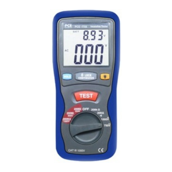
info@tursdaletechnicalservices.co.uk ② Data Hold Button ③ Lock Button ④ Backlight Button ⑤ Test Button ⑥ Rotary Function switch ⑦ VΩ Jack ⑧ COM input jack ⑨ Pothook ⑩ Battery Cover 4. BATTERY REPLACEMENT 4.1 How to connect test leads. a). On MΩ Range: Connect the red test lead into the “VΩ” terminal and the black lead into the “COM”... -
Page 7: Low Resistance (Continuity) Measurements
info@tursdaletechnicalservices.co.uk b). Measurements at 2000MΩ/1000V Some specifications require testing at 1000V. This voltage must also be selected where the supply voltage of the installation is between 500V and 1000V. First, set the range switch to 1000V and then proceed as indicated in a above for 500V testing. -
Page 8: Cables
info@tursdaletechnicalservices.co.uk the motor from the line. To test the brush rigging,field coils and armature connect one megohmmeter lead to the grounded motor housing and the other lead to the brush on the commutator. If the resistance measurement indicates a weakness,raise the brushes off the commutator and separately test the armature, field coils and brush rigging by connecting one megohmmeter lead to each of them individually, leaving the other connected to the grounded motor housing. - Page 9 info@tursdaletechnicalservices.co.uk In this direction will find a vision of the measurement technique: http://www.industrial-needs.com/measuring-instruments.htm NOTE: "This instrument doesn’t have ATEX protection, so it should not be used in potentially explosive atmospheres (powder, flammable gases)."...
Need help?
Do you have a question about the IT55 and is the answer not in the manual?
Questions and answers