Table of Contents
Advertisement
Quick Links
Advertisement
Table of Contents

Subscribe to Our Youtube Channel
Related Manuals for Emery Winslow 7600E

Summary of Contents for Emery Winslow 7600E
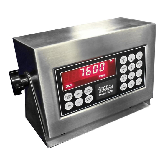
- Page 1 Model 7600E Digital Weight Display Configuration and Setup V4.31...
-
Page 2: Table Of Contents
TABLE OF CONTENTS SPECIFICATIONS ............ 4 DIMENSIONS……………………………………………5 INSTALLATION ............6 SETUP ACCESS ............7 MENU LAYOUT ............8 CONFIGURATION ............ 9 CALIBRATION ............11 REMOTE SERIAL DISPLAY ........12 SERIAL PORTS ............ 14 SERIAL COMMANDS ..........15 ANALOG OUTPUT ..........17 DIGITAL INPUT/OUTPUT ........ - Page 3 Emery Winslow Scale Company 73 Cogwheel Lane 4530 North 25th Street Seymour, CT 06483 Terre Haute, IN 47805 (203) 881-9333 (812) 466-5265 (203) 881-9477 FAX (812) 466-1046 FAX Alternate Packaging for extreme wash-down and with Totalizer in common enclosure...
-
Page 4: Specifications
SPECIFICATIONS LOAD CELL A/D CONVERTER TYPE: 24 bit delta sigma (1:16,777,216) EXCITATION: 5 VDC, 120 mA max. SIGNAL INPUT: 16 mv SENSITIVITY: 0.1 uV/grad UPDATE RATE: 30 update/second DISPLAY: Six (6) Decades, 0.6 inch LED KEYPAD: Full numeric plus controls POWER INPUT: 117/217 VAC, 50 ‑... -
Page 5: Dimensions
DIMENSIONS... -
Page 6: Installation
INSTALLATION POWER WIRING: The indicator is designed to be operated from 117/217 VAC, 50‑60 Hz. The unit power cord must be plugged into a grounded 3 ‑ wire polarized AC wall socket. All normal wiring and grounding precautions should be observed, including use of a "clean"... -
Page 7: Setup Access
SETUP ACCESS: To access instrument configuration, calibration or to enable op- tions, depress the “ZERO” key for five seconds. The Audit Trail counters (“Pxxxx” and “Cxxxx”) are displayed first followed by access code request (“AC?”). The initial factory setting is “0000” which is entered with four numeric “0”’s and enter (“ENT”). -
Page 8: Menu Layout
MENU LAYOUT (SEL.XXX) Configuration: Divisions, count by, decimal, over range, filter, AZM, zero range, motion, lb/kg, tare select, serial port selection, digital input enable, remote display, test mode, dual channel sum. Calibration: Zero, Span (Earlier units have ‘CAL’ prompt) Analog Output Setpoint - Digital I/O Time and date Weigh-IN / Weigh-OUT Truck mode... -
Page 9: Configuration
CONFIGURATION: “SEL.CFG” 1. Press and hold the ‘ZERO’ button for 10 seconds until a ‘P XX’ is displayed, then release. [Note: Limited configuration parameters (non-metrological) can be accessed by pressing and holding ‘PRINT/7’ key for 4 seconds.] 2. Wait for ‘C XX’ prompt, then the Access Code ‘AC ?’ prompt. Enter four (4) zeros ‘0000’... - Page 10 1, 2, 3, 4, 5, 6, 8, 10, 12, 15...90 Digital filter selection (averaging) off, 0.5, 1, 3, 5, 10 (divisions) Auto Zero Maintenance (AZM) Zero range selection:1.9% of 2,000 x 1.9, 5, 10, 20, FS (% of capacity) 0.2 = 38.0 lb Zero’s scale on power-up off, on (ISM) off, 1, 3, 5,10 (divisions)
-
Page 11: Calibration
CALIBRATION “SEL.CL1 (or SEL.CAL): (CL1/CL2 if dual channels are used): Note: Scale zero (dead load) and span adjust (single or multi-point) are independent. Therefore either can be done and repeated as necessary before exciting calibration. If an error has been made, exiting without “storing” will return to prior setup. -
Page 12: Remote Serial Display
REMOTE SERIAL DISPLAY OPTION In RSD mode the indicator can be set to work as a master or slave. Communica- tion is pre-set for Channel 2 only on both units. (RS232, 9600, 8, none) In RSD, re-access requires using the internal “cal” switch. Remote unit can have full or partial control of the main unit. - Page 13 Master/Slave sample configuration: (Master) Parameters CONFIGURATION PARAMETER DEFAULT CUSTOM DEFINITION REMOTE SERIAL DISPLAY rd.of, rd.re, rd.En Rd.re PRINT SELECTION SEE BELOW (Slave) Parameters CONFIGURATION PARAMETER DEFAULT CUSTOM DEFINITION REMOTE SERIAL DISPLAY rd.of, rd.re, rd.En Rd.En En.On Allow remote keypad operation Zr.On Enable/Disable zero key tr.On...
-
Page 14: Serial Ports
SERIAL PORTS Port 1: RS232 duplex (Rx, Tx), 20ma (Tx). See OPT 2 for additional commands Port 2: RS232 duplex (Rx, Tx), 20ma (Rx,Tx), RS485, or RS422. Basic functions only (Z, N, T, etc Note: Position jumper on J2 for Port 2 receive mode. TB-2 Tx1, RS232 Rx1, RS232... -
Page 15: Serial Commands
SERIAL COMMANDS “Gross” mode, no motion, inside zero range. <Z><cr> Zero Scale From “Gross” mode with Tare stored. <N><cr>Switch to Net From “Net” mode. <G><cr>Switch to Gross Switch to Net, no motion, not at “Gross” zero. <T><cr> Auto Tare <P><cr>Print Valid display, No motion <U><cr>Units Selects alternate units... - Page 16 G/N: One (1) character field data identification for weighing mode in continuous (computer) mode. Gross Mode = “G” (ASCII 071), Net Mode = “N” (ASCII 078) status: One (1) character data identification used in the continuous (computer) out- put mode to identify the status of the indicator. Characters are listed below in order of priority.
-
Page 17: Analog Output
OPTION 1: Analog Output J1,2: set jumper position 1-2 for 0-10 vdc set jumper position 2-3 for 4-20 ma Output Option 1 Analog Output: “SEL.OP1” Use Gross/Net to enter the menu and step to each category, Tare Recall to select parameters. -
Page 18: Digital Input/Output
OPTIONS 2: Digital IN/OUT (DIO) AC Inputs: D1, D2 are not installed, J1 = short (underside), J2 = open, R1 – R4 = 18k (3w, 5%, flame proof). (STANDARD) DC Inputs: D1, D2 are installed, J1 = open (cut trace), J2 = short, R1 –... -
Page 19: Setpoints, Batching
(SEL.OP2) SETPOINT CONFIGURATION __________________________________________________________________________ The 7600E Digital Weight Indicator is available with four (4) control inputs and four (4) control outputs when equipped with the optional Digital Input/Output (DIO) module. Setpoint outputs can be configured in the following modes: • Four independent setpoints with pre-act. (V3.98.0 and later) •... - Page 20 DEFINING SETPOINT PARAMETERS PARAMETER DESCRIPTION OUTPUT CHANGE Setpoint Weight value desired (Target) at end of weighing WT > or = SP operation. Pre-act Weight value which is set to allow for material in suspen- WT > or = SP - Pr sion Dribble Weight value at which...
- Page 21 PARAMETER ‘SEL.OP2’ (SETPOINT OPERATION) GROSS TARE RECALL PARAMETER SUBPARAMETER DEFINITION SELECTION DATA SELECTION Setpoints "Off". Zero Band (Parameter "10") is still functional Setpoint mode 2.0 OFF Over/Under (Check weighing mode) bAt1 Manual Batch mode, pauses between setpoints bAt2 Automatic Batch mode, continues without pause between setpoints (2.0 SP) SETPOINT OPERATION (Straight Setpoints)
- Page 22 PARAMETER ‘SEL.OP2’ (SETPOINT OPERATION) GROSS TARE RECALL PARAMETER SUBPARAMETER DEFINITION SELECTION DATA SELECTION (2.0 oU.Un) SETPOINT OPERATION (Over/Under) Setpoint - "OFF" Hi/Lo band Target with +/- band Check Weigher 1 Check Weigher 2 Check Weigher 3 Setpoint tracks GROSS weight only NET weight only Displayed weight Setpoint 1 is OFF when Lo...
- Page 23 PARAMETER ‘SEL.OP2’ (SETPOINT OPERATION) GROSS TARE RECALL (2.0 Bat1) SETPOINT OPERATION (Manual Batch) Setpoint 1 - "OFF" Setpoint 1 S1.P Setpoint 1 with Pre-Act S1.d Setpoint 1 with Dribble S1.P.d Setpoint 1 with Pre-Act and Dribble Setpoint 1a, 1b – Two/Four independent setpoints with Pre-Act DUAL Setpoint1 tracks GROSS weight only...
- Page 24 PARAMETER ‘SEL.OP2’ (SETPOINT OPERATION) GROSS TARE RECALL (2.0 Bat2) SETPOINT OPERATION (Auto Batch) Setpoint 1 - "OFF" Setpoint 1 S1.P Setpoint 1 with Pre-Act S1.d Setpoint 1 with Dribble S1.P.d Setpoint 1 with Pre-Act and Dribble Setpoint 1a, 1b – Two/Four independent setpoints with Pre-Act DUAL Setpoint1 tracks GROSS weight only...
- Page 25 FUNCTIONAL DESCRIPTION – Four setpoint (DUAL) setpoint mode DUAL mode is the (four independent) setpoint operation mode, where cutoff occurs when the weight is greater than or equal to ( ) the setpoint value. A. Push the “SET” key. B.
- Page 26 FUNCTIONAL DESCRIPTION – Straight setpoint mode SP mode is the setpoint (SP) operation mode, where cutoff occurs when the weight is greater than or equal ( ) to the setpoint (SP). Zero Band output is available. A. Push the “SET” key. B.
- Page 27 FUNCTIONAL DESCRIPTION – Pre-act mode PR adds a "pre-act" value which allows for "in-flight" material compensation. The cutoff occurs when the weight is greater than or equal to () the setpoint (SP) value minus the pre-act (Pr) value. Note: This allows changes in setpoint values while maintaining the pre-act setting. Zero band output is available.
- Page 28 FUNCTIONAL DESCRIPTION – Dribble mode Dribble mode adds a "dribble" (dr) which provides a "two-speed" (fast feed, slow feed) cutoff to enhance accuracy. The basic setpoint is used for slow feed, while the additional cutoff (fast feed) occurs when the weight is greater than or equal to () the setpoint minus the dribble value. Note: This allows changes to the setpoint target value while maintaining the same amount of fast to slow feed differential.
- Page 29 FUNCTIONAL DESCRIPTION – Dribble mode with Pre-act Provides both a dribble (dr) and preact (Pr) to setpoint configuration. The slow feed cutoff occurs when the weight is greater than or equal to () the setpoint minus the pre-act value. The fast feed cutoff occurs when the weight is greater than or equal to () the setpoint minus the pre-act and minus the dribble value.
- Page 30 FUNCTIONAL DESCRIPTION – Over/Under Hi/Lo mode Provides High, Low, and Accept outputs with the Low level ON when the weight is less than (<) Lo setpoint (SP LO), the High level ON when the weight is greater (>) than Hi setpoint (SP HI), and Accept is ON in between.
- Page 31 FUNCTIONAL DESCRIPTION – Over/Under Target mode Provides High, Low, and Accept outputs the same as direct entry above, except that a direct entry is made only for a target weight and High/Low settings become dependent upon that weight. The Low level is ON when the weight is less than (<) the Target minus the (Lo) value.
- Page 32 FUNCTIONAL DESCRIPTION – Over/Under Ck1 Provide Check-Weigh outputs for ‘Within Target Range’, ‘Within Acceptable Range’, and ‘Out of Bounds Range’. Direct entry is made only for a Target value (Ck-cnt) while the Acceptable and Out of Bounds settings become dependent upon that weight. Function of the bar graph as follows: If weight is within acceptable (Target) range, ‘Within Target’...
- Page 33 FUNCTIONAL DESCRIPTION – Over/Under Ck2 Same function as CK1 with the exception - Function of the bar graph as follows: Only one bar graph segment is ON at a time. Either ‘Out LO’, ‘Accept LO’, ‘Within Target’, Accept HI’, ‘Out HI’. Zero band output is available.
- Page 34 FUNCTIONAL DESCRIPTION – Over/Under Ck3 Provides Check-Weigh outputs for ‘Within Acceptable Range’, and ‘Out of Bounds Range’. Direct entry is made only for a Target value (Ck-cnt) while the ‘Acceptable’ setting becomes dependent upon that weight. Function of the bar graph as follows: If weight is within acceptable range, ‘Within Target’...
- Page 35 Bat1 - FUNCTIONAL OPERATION - "MANUAL BATCHING" MODE The "Manual Batching" Mode operates as follows: A. The ‘START/STOP’ key is pushed. B. The "Setpoint" indicator LED turns "On". C. The unit automatically switches to the "NET" weighing mode. (If configured for NET batching.) D.
- Page 36 Bat2 - FUNCTIONAL OPERATION - "AUTOMATIC BATCHING" MODE The "Automatic Batching" Mode operates as follows: A. The ‘START/STOP’ key is pushed. B. The "Setpoint" indicator LED turns "On". C. The unit automatically switches to the "NET" weighing mode. (If configured for NET batching.) D.
- Page 37 “SEL.OP2”. Select the operating mode for “Setpoint”, “Over/Under”, “Manual or Auto Batch”. After setup, the parameters for the selection are entered from the weighing mode. Use Gross/Net to enter the menu and step to each category, Tare Recall to select parameters. ENT to return to menu selection.
-
Page 38: Serial Communication (Setpoint/Accumulator)
Additional Serial Commands: Setpoint/Accumulator Totalizer/Accumulator reset command. Send TC<CR> to reset the totalizer, and the meter responds with a TC+<CR><LF> string. Port 1 only. Ten/Nine-digit Accumulator Printing/Serial Format Output: Description COMMAND Output 10/9-digit w/ printable units (e.g., lb or kg) “... -
Page 39: Time & Date
OPTION 3: Time and Date Time & Date ---, 24H, 12A, 12P Skip time, 24 hour, 12 hour am, 12 hour pm Set time: hh mm ss Set date: mm dd yy Month print selection, short numerical (mm/ dd/yy), number 01 thru 12, month S.no, no, Let spelled out Off, Un, Ab, On... -
Page 40: Weigh In/Out
OPTION 4: Weigh – In / Weigh – Out Truck Scale Application: Provides six digit Identification. Operates in “Gross” only. This mode provides a system for single scale applications to determine net weight by storing incoming weight and completing the transaction with out going weight. Off, On Turn on Weigh–in / Weigh-out Yes, No... - Page 41 Full Truck IN Truck enters scale full, scale indicates “Stable”. Operator inserts ticket and pushes “Print” key. Display responds with “Id no” prompt. Operator enters truck “ID Number”, up to 6 digits. Operator pushes “Ent” key. Printer prints: Time/Date (optional) (xxxxxx) ID.
- Page 42 Gross only printout: 22380 lb GR Keyed Tare: 8900 ID. No. 22380 lb GR 100 lb TR KEYED 22280 lb NT Note: All lines are terminated with CR/LF Transaction Buffer: Select / Print / Clear / Clear All Select ID: With ID displayed, user can select a stored ID by pressing Set to select the last record or Tare for next if tare is not enabled (4.8).
-
Page 43: Ten Point Linearization
OPTION 5: Ten Point Calibration Allows up to 10 span points (pt1……pt10). Zeroing the scale clears the existing values. Points are assigned incrementally with error indication if the addition is not above the prior point or exceeding scale capacity. Filter selection included for rolling or box averaging. OFF, On Enable 10 point span A : Rolling average... -
Page 44: Smart Serial
OPTION 7: Smart Serial I/O The SMART SERIAL I/O option now offers a wide degree of flexibility for an opera- tor to customize the serial output format for individual system requirements. The custom print currently supports: • Specifying starting and terminating characters (stx, cr, lf, etc.). - Page 45 STANDARD SERIAL CONFIGURATION: The SMART SERIAL I/O Option allows standard serial output ports to be modified and imported into the serial output data stream. CUSTOM PROTOCOL FILE SELECTION: The selection of the associated custom print file is performed automatically by serial port and the data mode (GROSS, NET, TOTAL RECALL, or SPECIAL) that the instrument is currently in at the time of a print.
- Page 46 NORMAL TRUCK MODE MODE Truck Mode Out- put Port is Gross data selected under option 4, Port 1 Port 1 Net data selection mirrors Port 2 below. Total data Special Truck Entry Gross data Port 2 Truck Out Empty Net data Truck Out Full Total data Truck Fixed Tare...
- Page 47 Example : A header stating the company's name Scrap inc. is desired when Port 1 outputs GROSS mode weight data. Printout = Scrap inc. 30000 LB GR 05/13/2005 12:30am PRINT FILE 1 (7.1 - Port 1 "GROSS" mode data) LINE # CODE CODE definition STX (start of text)
- Page 48 CUSTOM PRINT FILES REMOTE READ AND WRITE SSC (Smart Serial Codes) command is provided to read or write buffer data 7.1...7.16. Example: Read from memory: SSC<CR> SSC 1 2 600 200 32 601 13 10 999 SSC 9 83 99 114 97 112 32 105 110 99 46 13 10 999 SSC 10 402 32 401 999 Example: Write to memory: SSC<sp><X><yyy><yyy><cr>...
- Page 49 CONTROL CONTROL SYMBOLS NUMBERS CHAR CODE CHAR CODE CHAR CODE CHAR CODE “ & ‘ < >...
- Page 50 UPPER CASE UPPER CASE LOWER CASE LOWER CASE CHAR CODE CHAR CODE CHAR CODE CHAR CODE...
- Page 51 CODE DESCRIPTION CODE DESCRIPTION GROSS WT &’LB/KG GR’ TRUCK GROSS ‘LB/KG GR’ GROSS WT & ‘LG/KG’ TRUCK GROSS ONLY TRUCK TARE ‘LB/KG TR’ GROSS WT GROSS WT (no 0 blanking) TRUCK TARE ONLY TRUCK NET ‘LB/KG NT’ PA Gross mode TRUCK NET ONLY NET WT &...
-
Page 52: Display Messages
DISPLAY MESSAGES MESSAGE DESCRIPTION D/A card detected - Displayed under the check function. IIC short - Power-up hardware failure indication. IIC.ERR EEPROM is reset by EER command - Power-up message Displayed on power-up when the DC power push-button is AUTO EEPROM is reset - Power-up message ERR6.x Key-pad key is stuck. -
Page 53: 115/220 Vac
115 to 220 VAC CONVERSION EW1000U Bottom side, directly under the transformer. Add Jumper Cut Clad... -
Page 54: Spare Parts
4-20 mA Analog Output PA-57818 Setpoint AC input, specify output PA-57880 Setpoint DC input, specify output PA-57834 Second Channel PA-57869A Ethernet Option Parts may be ordered from: Emery Winslow Scale Company, 73 Cogwheel Lane, Seymour, CT 06843 203-881-9333x124 FAX: 203-881-9477 E-mail: homeoffice@emerywinslow.com... -
Page 55: Digital Configuration Record
7600E DIGITAL CONFIGURATION RECORD Customer: Capacity Date: System Number: Serial Number: Excitation: SO Number: FIRMWARE: 4.31 CONFIGURATION PARAMETER DEFAULT CUSTOM Definition 5000 5000 FULL SCALECAPACITY 0.001, 0.002, 0.005 …. 100, 200, 500 DISPLAY RESOLUTION, DP OVER RANGE 105%, 9 DIVISIONS... - Page 56 CONFIGURATION ANALOG OUTPUT (OPTION) Option 1 PARAMETER DEFAULT CUSTOM Definition ANALOG TRACKS GROSS, NET, DISPLAY ANALOG OUTPUT ZERO VALUE 5000 ANALOG OUTPUT FULL SCALE VALUE TRIM : ‘TARE’ TO INCREASE, ZERO ‘GR/NET’ TO DECREASE VALUE TRIM : ‘TARE’ TO INCREASE, SPAN ‘GR/NET’...
- Page 57 CONFIGURATION 10 POINT LINEARIZATION / FILTER / RANGES Option 5 PARAMETER DEFAULT CUSTOM Definition ENABLE 10 POINT SPAN OFF, ON FILTER AVERAGE SELECT A: ROLLING, B:BOX MULTI-RANGE SELECT CONSULT FACTORY CONFIGURATION ACCUMULATOR Option 6 PARAMETER DEFAULT CUSTOM Definition ENABLE ACCUMULATOR OFF, ON, AUTO FILTER AVERAGE SELECT A: ROLLING, B:BOX...
- Page 58 Notes:...
- Page 60 PROUDLY MADE IN THE UNITED STATES OF AMERICA SINCE 1868...
Need help?
Do you have a question about the 7600E and is the answer not in the manual?
Questions and answers