
Related Manuals for PROEL DBE108E


Summary of Contents for PROEL DBE108E
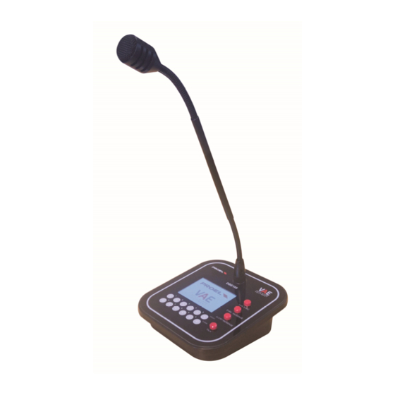
- Page 1 DBE108E Ethernet Desk Call Station Postazione Microfonica da Tavolo Ethernet USER’S MANUAL MANUALE D’USO ENGLISH ITALIANO 96MAN0164-REV.04/22...
-
Page 2: Important Safety Instructions
IMPORTANT SAFETY INSTRUCTIONS Watch for these symbols: The lightning flash with arrowhead symbol within an equilateral triangle is intended to alert the user to the presence of uninsulated “dangerous voltage” within the product’s enclosure, which may be of sufficient magnitude to constitute a risk of electric shock to persons. -
Page 3: Disposal Of Old Electrical & Electronic Equipment
2015/863/EU, WEEE Directive 2012/19/EU. CONDITIONS OF USE Proel do not accept any liability for damage caused to third parties due to improper installation, use of non-original spare parts, lack of maintenance, tampering or improper use of this product, including disregard of ascertainable and applicable safety standards. -
Page 4: Table Of Contents
SUMMARY IMPORTANT SAFETY INSTRUCTIONS ......................2 DISPOSAL OF OLD ELECTRICAL & ELECTRONIC EQUIPMENT ................. 3 DECLARATION OF CONFORMITY ........................3 CONDITIONS OF USE ........................... 3 PACKAGING, SHIPPING AND COMPLAINT ....................3 WARRANTY AND PRODUCTS RETURN ......................3 INTRODUCTION ............................5 DESCRIPTION .............................. -
Page 5: Introduction
The connection is made via a UTP Cat. 5 cable in a computer network together with other DBE108E bases, in addition to voice alarm systems. -
Page 6: Rear Panel Connections
“UP” e “DOWN” Scrolling Up and Down touch buttons. “1”…”8” Group selection touch buttons. REAR PANEL CONNECTIONS On the rear panel there is the power jack connector and the 10/100 Ethernet port. 1. Power supply connector 18 ÷ 24Vdc (+ internal, - external) - 0.6 A. ATTENTION: use only the supplied power supply unit. -
Page 7: Description Of The Windows Displayed On The Touch Screen
DESCRIPTION OF THE WINDOWS DISPLAYED ON THE TOUCH SCREEN By starting the microphone station in configuration mode (see next chapter) and pressing the "Labels" at the top of touchscreen, you will be able to access the 7 windows corresponding to specific functions. If instead you access the microphone station in standard user mode, some windows will not be available. -
Page 8: Alert Msg
ALERT MSg From this window it is possible to send each of the connected Evac units its own Alert Message. Note: refer to the USING THE MICROPHONE STATION chapter and following. PAGING From this window it is possible to make paging calls on the single zones or groups of the different Evac units. -
Page 9: Status
Once the DBE108E is inserted into a network together with the EVAC devices and after self-configuration, the DBE108E will start monitoring them. In case of lack of connection between the control panels and the DBE108E, a Fault Warning will be generated. In particular, we can distinguish two cases: •... -
Page 10: Config
This page is displayed only in configuration mode. Note: for the use of this function, refer to the CONFIGURATION OF INITIAL START-UP chapter. INFO The assignments made during the programming of the various buttons and groups of the DBE108E are here summarized. NOTE This page is displayed only in configuration mode. -
Page 11: Configuration Of Initial Start-Up
The DBE108E must be plugged into a network where an Ethernet Switch with DHCP Server function is present and active. The DBE108E is designed to work with both AE300 and / or AE604 for a total of 8 Evac units. -
Page 12: Manual Configuration Of The Buttons
In the example, 4 buttons are assigned to the AE604-1 for zones 1..4, 1 button for the AE300-1 and 4 other buttons to the AE604-2. NOTE Once the DBE108E bases have been programmed, by disconnecting or reconnecting the bases or the various Evac units, the acquisition order of the Evac units remains unchanged. MANUAL CONFIGURATION OF THE BUTTONS Pressing the "CONFIG"... - Page 13 The name of the EVAC system is that one set on the Evac unit from the “Ethernet menu”: for details, see the Evac unit manual. Once the control unit has been selected, open the flag menu that identifies the buttons associated with the Evac unit.
-
Page 14: Configuration Of A Group
To make the settings effective, before selecting another Evac unit or configuring another button from the drop-down menu, press the "STORE" button. CONFIGURATION OF A GROUP The microphone console has 8 call GROUPS which can be called up directly from the buttons on the panel. By pressing the GROUP "n"... -
Page 15: Use Of The Microphone Station
In this way, the base will work in standard mode for the end user. To facilitate the user, the DBE108E allows you to make an emergency call, paging or play messages on all zones without operating on the touch-screen display: EMERGENCY CALL Press the LIVE EVAC button and then the TALK button. -
Page 16: Using The Touch Screen To Make Calls Or Send Pre-Registered Messages
“CANCEL” button. Note: in the case of several DBE108E bases connected to the network, if a base is sending a message in "LIVE EVAC" on one or more Evac units, the zone buttons of the Evac units involved in the other bases connected (always at the "LIVE EVAC"... -
Page 17: Evac Msg
“CANCEL” button. Note: in the case of several DBE108E bases connected to the network, if a base is reproducing a message in "EVAC MSg" on one or more Evac units, in the other connected bases (always at the "EVAC MSg" level) the zone buttons of the Evac units involved will be gray color, to indicate that they are in use, and it will not be possible to make the announcement on these Evac units until the other operator has finished. -
Page 18: Alert Msg
“CANCEL” button. Note: in the case of several DBE108E bases connected to the network, if a base is reproducing a message in "ALERT Msg" on one or more Evac units, in the other connected Bases (always at the "ALERT Msg" level) the zone buttons of the Evac units involved will be gray color, to indicate that they are in use, and it will not be possible to make the announcement on these Evac units until the other operator has finished. -
Page 19: Paging
“CANCEL” button. Note: in the case of several DBE108E bases connected in the network, if a base is sending a Paging message on one zone or more zones, in the other connected Bases (always at Paging level) the zone buttons of the entire control units involved will be gray, to indicate that are in use, and it will not be possible to announce on these exchanges until the other operator has finished. -
Page 20: Technical Specification
TECHNICAL SPECIFICATION Model: DBE108E Sensitivity: -55dB ± 3dB Frequency Response: 400Hz ÷ 8KHz (-3dB) Dynamic range: 72dB Gooseneck type: Dynamic Gooseneck length: 390 mm I/O Connector: 1x Ethernet 10/100 Power supply: 18÷24Vdc – 0.6A Dimensions (W x H x D):... -
Page 21: Importanti Istruzioni Di Sicurezza
IMPORTANTI ISTRUZIONI DI SICUREZZA Fai attenzione a questi simboli: Il simbolo del fulmine con freccia all'interno di un triangolo equilatero avverte l'utente della presenza di “voltaggio pericoloso” all'interno del prodotto, che possono essere di intensità sufficiente a costituire un rischio di folgorazione per le persone. -
Page 22: Smaltimento Di Vecchie Attrezzature Elettriche Ed Elettroniche
2011/65/EU e 2015/863/EU, Direttiva WEEE 2012/19/EU. CONDIZIONI DI UTILIZZO Proel non si assume alcuna responsabilità per danni causati a terzi a causa di installazione impropria, uso di ricambi non originali, mancanza di manutenzione, manomissione o uso improprio di questo prodotto, incluso il mancato rispetto di standard di sicurezza accertabili e applicabili. - Page 23 SOMMARIO IMPORTANTI ISTRUZIONI DI SICUREZZA ....................21 SMALTIMENTO DI VECCHIE ATTREZZATURE ELETTRICHE ED ELETTRONICHE ..........22 DICHIARAZIONE DI CONFORMITÀ ......................22 CONDIZIONI DI UTILIZZO ........................... 22 IMBALLAGGIO, TRASPORTO E RECLAMI ..................... 22 GARANZIE E RESI ............................22 INTRODUZIONE ............................24 DESCRIZIONE .............................
-
Page 24: Introduzione
(riferimento 1). IMPORTANTE: Ai fini del collegamento e della messa in funzione, la DBE108E è un dispositivo di rete ethernet a tutti gli effetti e non una apparecchiatura audio. Presa per la connessione del Microfono in dotazione. -
Page 25: Pannello Posteriore Connessioni
“UP” e “DOWN” Tasti Touch per lo scorrimento verso sopra e verso sotto. “1”…”8” Tasti Touch per la selezione dei GRUPPI. PANNELLO POSTERIORE CONNESSIONI Sul pannello posteriore è presente il connettore jack di alimentazione e la porta Ethernet 10/100. 3. Connettore alimentazione 18 ÷ 24Vdc (+ interno, - esterno) - 0,6 A. ATTENZIONE: usare esclusivamente l’alimentatore in dotazione. -
Page 26: Descrizione Delle Finestre Visualizzate Sul Touch Screen
DESCRIZIONE DELLE FINESTRE VISUALIZZATE SUL TOUCH SCREEN Avviando la Consolle Microfonica nella modalità di configurazione (vedi capitolo successivo) e premendo sul touch-screen le rispettive “Etichette”, si potrà accedere alle 7 finestre a cui corrispondono specifiche funzioni. Nel caso si acceda invece in modalità utente standard, alcune finestre non saranno disponibili. LIVE EVAC Da questa finestra è... -
Page 27: Alert Msg
ALERT MSg Da questa finestra è possibile inviare a ciascuna delle centrali Evac collegate il proprio Messaggio di Allerta. Nota: fare riferimento al capitolo USO DELLA POSTAZIONE MICROFONICA e successivo. PAGING Da questa finestra è possibile effettuare chiamate vocali di Servizio sulle singole zone o gruppi delle diverse centrali Evac. -
Page 28: Status
Una volta che la DBE108E viene inserita in una rete insieme agli apparati EVAC e dopo l’autoconfigurazione, la DBE108E inizierà a monitorarli. In caso di mancanza di connessione tra le centrali e la DBE108E verrà generato un Fault Warning. In particolare, possiamo distinguere due casi: •... -
Page 29: Config
Nota: per l’utilizzo di questa funzione riferirsi al capitolo CONFIGURAZIONE DI AVVIO INIZIALE. INFO Vengono riepilogate le assegnazioni fatte in fase di programmazione dei vari tasti e gruppi della DBE108E. NOTA Tale pagina è visualizzata solo nella modalità di configurazione. -
Page 30: Configurazione Di Avvio Iniziale
CONFIGURAZIONE DI AVVIO INIZIALE La DBE108E deve essere inserita in una rete dove è presente (e attivo) uno Switch Ethernet con funzione di Server DHCP. La DBE108E è predisposta per lavorare sia con AE300 e/o AE604 per un totale complessivo di 8 centrali. -
Page 31: Configurazione Manuale Dei Tasti
Nell’esempio sono assegnati 4 tasti alla AE604-1 per le zone 1..4, 1 tasto per la AE300-1 e altri 4 tasti alla AE604-2. NOTA Una volta programmate le basi DBE108E, disconnettendo o riconnettendo le basi stesse o le varie centrali Evac, l‘ordine di acquisizione delle centrali Evac resterà invariato. CONFIGURAZIONE MANUALE DEI TASTI Premendo sull’etichetta “CONFIG”... - Page 32 Il nome del sistema EVAC è quello inserito sulla centrale Evac dal “menu Ethernet”: per i dettagli vedere il manuale della centrale Evac. Selezionata la centrale, aprire il menu a bandiera che identifica i pulsanti associati alla centrale. Nel caso di AE604, saranno editabili 4 pulsanti: “BUTTON1”, “BUTTON2”, “BUTTON3”...
-
Page 33: Configurazione Di Un Gruppo
Per rendere effettive le impostazioni effettuate, prima di passare alla selezione di un’altra centrale Evac o alla configurazione di un altro pulsante dal menu a tendina premere sul tasto “STORE”. CONFIGURAZIONE DI UN GRUPPO La consolle microfonica dispone di 8 GRUPPI di chiamata che possono essere richiamati direttamente dai pulsanti sul pannello. -
Page 34: Uso Della Postazione Microfonica
In questo modo la base lavorerà in modalità standard per l’utente finale. Per agevolare l’utente, la DBE108E permette di fare una chiamata di emergenza, di paging o riprodurre i messaggi su tutte le zone senza operare sul display Touch-Screen: CHIAMATA DI EMERGENZA Premere il tasto LIVE EVAC e poi il tasto TALK. -
Page 35: Uso Del Touch Screen Per Effettuare Chiamate O Invio Messaggi Preregistrati
“CANCEL”. Nota: nel caso di più basi DBE108E collegate in rete, se una base sta inviando un messaggio in “LIVE EVAC” su una o più centrali, nelle altre Basi collegate (sempre a livello “LIVE EVAC”) i pulsanti di zona delle centrali coinvolte saranno di colore grigio, ad indicare che sono in uso, e non sarà... -
Page 36: Evac Msg
“CANCEL”. Nota: nel caso di più basi DBE108E collegate in rete, se una base sta riproducendo un messaggio in “EVAC MSg” su una o più centrali, nelle altre basi collegate (sempre a livello “EVAC MSg”) i pulsanti di zona delle centrali coinvolte saranno di colore grigio, ad indicare che sono in uso, e non sarà... -
Page 37: Alert Msg
“CANCEL”. Nota: nel caso di più basi DBE108E collegate in rete, se una base sta riproducendo un messaggio in “ALERT Msg” su una o più centrali, nelle altre Basi collegate (sempre a livello “ALERT Msg”) i pulsanti di zona delle centrali coinvolte saranno di colore grigio, ad indicare che sono in uso, e non sarà... -
Page 38: Paging
“CANCEL”. Nota: nel caso di più basi DBE108E collegate in rete, se una base sta inviando un messaggio di Paging su una zona o più zone, nelle altre Basi collegate (sempre a livello Paging) i pulsanti di zona delle intere centrali coinvolte saranno di colore grigio, ad indicare che sono in uso, e non sarà... -
Page 39: Specifiche Tecniche
SPECIFICHE TECNICHE Modello: DBE108E Sensibilità: -55dB ± 3dB Risposta in Frequenza: 100Hz ÷ 8KHz (-3dB) Gamma Dinamica: 72dB Tipo Microfono: Dinamico Lunghezza Gooseneck: 390 mm Connettore I/O: 1x Ethernet 10/100 Alimentazione: 18÷24Vdc - 0,6A Dimensioni (L x A x P):... - Page 40 PROEL S.p.A. (World Headquarters - Factory) Via alla Ruenia 37/43 64027 Sant’Omero (Te) – Italy Tel: +39 0861 81241 Fax: +39 0861 887862 www.proel.com...
Need help?
Do you have a question about the DBE108E and is the answer not in the manual?
Questions and answers