Table of Contents
Advertisement
Quick Links
Advertisement
Table of Contents

Summary of Contents for SiFive FE310-G000
- Page 1 SiFive FE310-G000 Manual Version 1.0.1 c SiFive, Inc.
- Page 2 SiFive FE310-G000 Manual, Version 1.0.1...
-
Page 3: Sifive Fe310-G000 Manual
fitness for a particular purpose and non-infringement. SiFive does not assume any liability rising out of the application or use of any product or circuit, and specifically disclaims any and all liability, including without limitation indirect, incidental, special, exemplary, or consequential damages. - Page 4 SiFive FE310-G000 Manual, Version 1.0.1...
-
Page 5: Table Of Contents
FE310-G000 Pins FE310-G000 Pinmux ........FE310-G000 Memory Map... - Page 6 SiFive FE310-G000 Manual, Version 1.0.1 Reset and Trap Vectors ....... . . 12 FE310-G000 Package Options 48-Pin QFN Package .
-
Page 7: Introduction
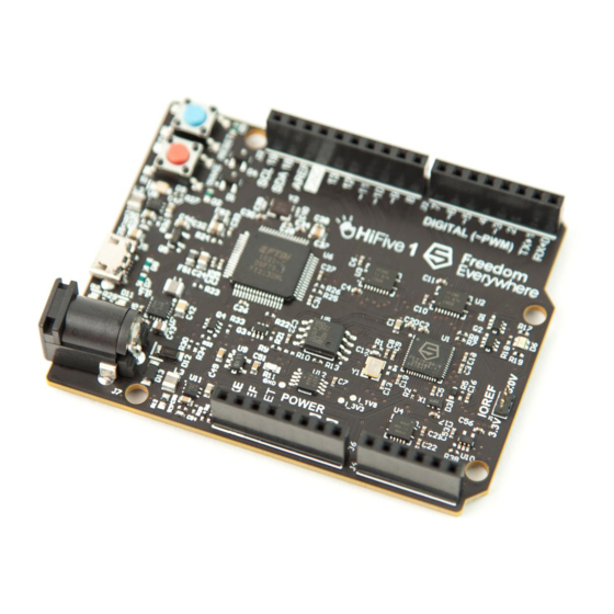
Chapter 1 Introduction The FE310-G000 is the first Freedom E300 SoC, and forms the basis of the HiFive1 development board for the Freedom E300 family. The FE310-G000 is built around the E31 Coreplex instantiated in the Freedom E300 platform, and the E3 Coreplex Series and Freedom E300 Platform manuals should be read together with this manual. -
Page 8: Clint
Watchdog Real-Time Clock Ticks LFROSC Reset Unit erst_n Figure 1.1: FE310-G000 top-level block diagram. CLINT The Coreplex-Local Interrupt Controller (CLINT) supports the standard timer and software inter- rupts. PLIC The platform-level interrupt controller (PLIC) receives interrupt signals from the peripheral devices and prioritizes these for service by the core. -
Page 9: Quad-Spi Flash
The dwakeup n input supports wired-OR connections of multiple wakeup sources. Power Supply FE310-G000 requires two dedicated power rails providing 1.8 V power to the always-on block and core logic, and 3.3 V to the I/O pads. - Page 10 SiFive FE310-G000 Manual, Version 1.0.1...
-
Page 11: Fe310-G000 Pins
Chapter 2 FE310-G000 Pins FE310-G000 Pinmux The GPIO pins on FE310-G000 support pin muxing functionality as described in the Freedom E300 Platform Reference Manual. Table 2.1 shows the multiple functions supported by each pin. Each pin is also an interrupt source. - Page 12 SiFive FE310-G000 Manual, Version 1.0.1 Table 2.1: FE310-G000 Pin Hardware I/O Functions Pin Number IOF0 IOF1 PWM0 0 PWM0 1 QSPI1:SS0 PWM0 2 QSPI1:SD0/MOSI PWM0 3 QSPI1:SD1-MISO QSPI1:SCK QSPI1:SD2 QSPI1:SD3 QSPI1:SS1 QSPI1:SS2 QSPI1:SS3 PWM2 0 PWM2 1 PWM2 2 PWM2 3...
-
Page 13: Fe310-G000 Memory Map
Chapter 3 FE310-G000 Memory Map Table 3.1 enumerates the peripherals included in FE310-G000 and where they are located in the memory map. Base Description (see E3 Coreplex Manual) 0x0000 0000 0x0FFF FFFF On-chip OTP read ( 8 KiB) 0x0002 0000... - Page 14 SiFive FE310-G000 Manual, Version 1.0.1...
-
Page 15: Fe310-G000 Interrupts
Chapter 4 FE310-G000 Interrupts Table 4.1 lists the PLIC interrupt sources in FE310-G000. The PLIC on FE310-G000 has a 3-bit programmable interrupt priority field on each interrupt source. Interrupt Number Source No Interrupt wdogcmp rtccmp uart0 uart1 qspi0 qspi1 qspi2... - Page 16 SiFive FE310-G000 Manual, Version 1.0.1...
-
Page 17: Fe310-G000 Boot
The debug RAM code can be used to bootstrap download of further code. Mask ROM (MROM) MROM is fixed at design time, and is located on the peripheral bus on FE310-G000 but instructions fetched from MROM are cached by the E31 core’s I-cache. The MROM contains an instruction at address 0x1000 which jumps to the OTP start address at 0x2 0000. -
Page 18: Quad Spi Flash Controller (Qspi)
SiFive FE310-G000 Manual, Version 1.0.1 Quad SPI Flash Controller (QSPI) The dedicated QSPI flash controller connects to external SPI flash parts that are used for execute- in-place code. SPI flash is not available in certain scenarios such as package testing or board designs not using SPI flash (e.g., just using on-chip OTP). - Page 19 If the OTP has been programmed, the core will begin executing core out of the OTP. If all components are working correctly, FE310-G000 will perform like a production E300 chip by fetching the first instruction from 0x1000. For FE310-G000 the instruction stored there jumps straight to OTP at 0x2 0000, and will either enter trap loop if the OTP is not programmed, or start running the OTP code.
- Page 20 SiFive FE310-G000 Manual, Version 1.0.1...
- Page 21 Chapter 6 FE310-G000 Package Options FE310-G000 is currently offered in a single package option, a standard QFN 48-pin package. 48-Pin QFN Package The pinout of the package is given in the following tables. Table 6.1: Power and Ground Connections for 48-pin QFN Package...
- Page 22 SiFive FE310-G000 Manual, Version 1.0.1 Table 6.3: Digital I/O Connections for 48-pin QFN Package Pin Number Name Type Description JTAG TCK Input JTAG Clock line for debug in- terface JTAG TDO Output JTAG Data Out for debug in- terface JTAG TMS...
- Page 23 Copyright c 2016, SiFive Inc. All rights reserved. Table 6.4: Always-On 1.8V I/O Connections for 48-pin QFN Package AON PMU OUT 1 Output 1.8V Programmable SLEEP con- trol. AON PMU OUT 0 Output 1.8V Programmable SLEEP con- trol. AON PMU DWAKEUP N Input 1.8V...
- Page 24 SiFive FE310-G000 Manual, Version 1.0.1...
- Page 25 Chapter 7 FE310-G000 Configuration String The initial version of the FE310-G000 has a configuration string of: /cs-v1/; model = \"SiFive,FE310G-0000-Z0\"; compatible = \"sifive,fe300\"; /include/ 0x20004;...


Need help?
Do you have a question about the FE310-G000 and is the answer not in the manual?
Questions and answers