HP Compaq dc7800 Series Technical Reference Manual
Business desktop computers
Hide thumbs
Also See for Compaq dc7800 Series:
- Reference manual (276 pages) ,
- Troubleshooting manual (70 pages) ,
- Quickspecs (67 pages)
Table of Contents
Advertisement
Technical Reference Guide
HP Compaq dc7800 Series
Business Desktop Computers
Document Part Number: 461444-001
October 2007
This document provides information on the design, architecture, function,
and capabilities of the HP Compaq dc7800 Series Business Desktop
Computers. This information may be used by engineers, technicians,
administrators, or anyone needing detailed information on the products
covered.
Advertisement
Table of Contents

Related Manuals for HP Compaq dc7800 Series


Summary of Contents for HP Compaq dc7800 Series
- Page 1 Document Part Number: 461444-001 October 2007 This document provides information on the design, architecture, function, and capabilities of the HP Compaq dc7800 Series Business Desktop Computers. This information may be used by engineers, technicians, administrators, or anyone needing detailed information on the products...
- Page 2 Adobe, Acrobat, and Acrobat Reader are trademarks or registered trademarks of Adobe Systems Incorporated. The only warranties for HP products and services are set forth in the express warranty statements accompanying such products and services. Nothing herein should be construed as constituting an additional warranty. HP shall not be liable for technical or editorial errors or omissions contained herein.
-
Page 3: Table Of Contents
2.4 Specifications............. . . 2–11 Technical Reference Guide www.hp.com Contents... - Page 4 5.7.2 Pointing Device Interface Operation ........5–10 www.hp.com...
- Page 5 7.4 Signal Distribution............7–10 Technical Reference Guide www.hp.com Contents...
- Page 6 8.7 Management Engine Functions ..........8–8 A Error Messages and Codes Index www.hp.com Technical Reference Guide...
-
Page 7: Introduction
About this Guide This guide provides technical information about HP Compaq dc7800 Business PC personal computers that feature Intel processors and the Intel Q35 Express chipset. This document describes in detail the system's design and operation for programmers, engineers, technicians, and system administrators, as well as end-users wanting detailed information. - Page 8 Introduction www.hp.com Technical Reference Guide...
-
Page 9: Serial Number
Serial Number The serial number is located on a sticker placed on the exterior cabinet. The serial number is also written into firmware and may be read with HP Diagnostics or Insight Manager utilities. Notational Conventions The notational guidelines used in this guide are described in the following subsections. -
Page 10: Common Acronyms And Abbreviations
Basic assurance test binary-coded decimal basic input/output system second/new revision Bayonet Neill-Concelman (connector type) bits per second Bootstrap processor Built to order column address strobe compact disk compact disk read-only memory compact disk system color graphics adapter www.hp.com Technical Reference Guide... -
Page 11: Acronyms And Abbreviations
Digital video interface Double word (32 bits) extended display identification data extended data out (RAM type) electrically erasable PROM enhanced graphics adapter Electronic Industry Association extended ISA enhanced parallel port enhanced IDE www.hp.com Introduction... - Page 12 Hertz (cycles-per-second) I/O controller hub integrated drive element Institute of Electrical and Electronic Engineers interrupt flag interface integrated graphics controller inch interrupt input/output initial program loader Infrared Data Association interrupt request industry standard architecture www.hp.com Technical Reference Guide...
- Page 13 Non-return-to-zero inverted nanosecond nested task flag National Television Standards Committee non-volatile random access memory operating system 1. programmable array logic 2. phase alternating line Parallel ATA www.hp.com Introduction...
- Page 14 Read/Write Serial ATA small computer system interface Singles data rate (memory) Synchronous Dynamic RAM Serial digital video output Single Edge-Connector sequential colour avec memoire (sequential color with memory) sign flag www.hp.com Technical Reference Guide...
- Page 15 Telecommunications Information Administration twisted pair ethernet track per inch transistor-transistor logic television transmit universal asynchronous receiver/transmitter Ultra DMA Uniform resource locator microsecond Universal Serial Bus unshielded twisted pair volt www.hp.com Introduction...
- Page 16 Table 1-1 (Continued) Acronyms and Abbreviations Description Volts alternating current Volts direct current Video Electronic Standards Association video graphics adapter very large scale integration Video RAM watt Wake-On-LAN Windows RAM zero flag zero insertion force (socket) www.hp.com Technical Reference Guide...
-
Page 17: System Overview
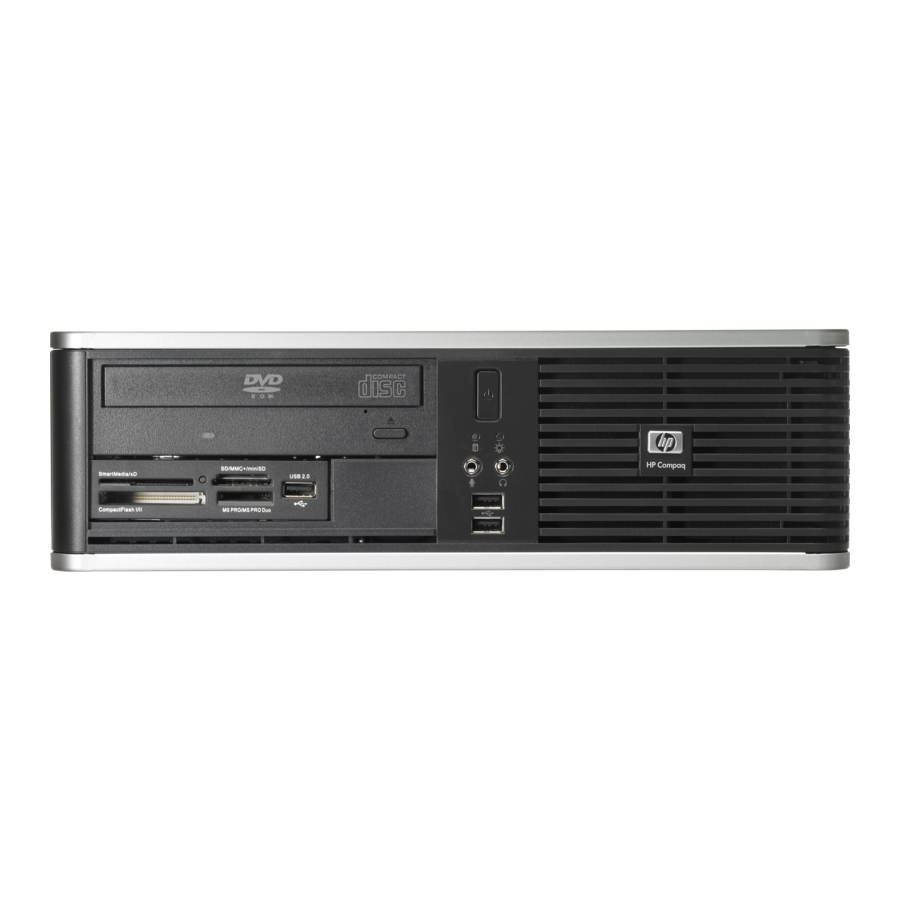
Introduction The HP Compaq dc7800 Business PC personal computers (Figure 2-1) deliver an outstanding combination of manageability, serviceability, and compatibility for enterprise environments. Based on the Intel processor with the Intel Q35 Express chipset, these systems emphasize performance along with industry compatibility. These models feature a similar architecture incorporating both PCI 2.3 and PCIe buses. -
Page 18: Features
Hoodlock (SFF and CMT form factors only) ❏ USB port disable ■ PS/2 enhanced keyboard ■ PS/2 optical scroll mouse ■ Energy Star 4.0 with 80 Plus compliancy standard on USDT form factors (option available on SFF and CMT form factors) www.hp.com Technical Reference Guide... - Page 19 2 SODIMM 4 DIMM 1 std., 1 opt. [1] 1 [3] [4] 1 [2] 2 [3] 1 half-height 2 full-height [6] external internal 135-watt 240-watt www.hp.com System Overview 4 DIMM 1 std., 1 opt. [1] 1 [5] full-height internal 365-watt...
-
Page 20: System Architecture
[3] Low-profile slot in standard configuration. 2 full-height slots supported with optional PCI riser. [4] 2nd serial port possible with optional adapter. Table 2-2. USDT 2 SODIMMs 4 DIMMs Yes [1] 1 [2] 2 [1] 1 [3] 1 [4] www.hp.com 4 DIMMs 1 [4] Technical Reference Guide... - Page 21 [3] 0 slots in USDT, 1 or 2 slots in SFF, 3 slots in CMT [4] 1 MiniCard slot in USDT, 2 slots in SFF, 2 slots in CMT [5] 8 ports accessible externally, 2 ports accessible internally Figure 2-2. HP Comapq dc7800 Business PC Architecture, Block diagram Technical Reference Guide Intel...
-
Page 22: Intel Processor Support
The processor heatsink/fan assembly mounting differs between form factors. Always use the same assembly or one of the same type when replacing the processor. Refer to the applicable Service Reference Guide for detailed removal and replacement procedures of the heatsink/fan assembly and the processor. www.hp.com Technical Reference Guide... -
Page 23: Chipset
PCI 2.3 bus I/F PCI Express x1 LPC bus I/F SMBus I/F SATA I/F HD audio interface RTC/CMOS IRQ controller Power management logic USB 1.1/2.0 controllers supporting 12 ports (these systems provide 8 external, 2 internal) Gigabit Ethernet controller www.hp.com System Overview... -
Page 24: Support Components
Power supply voltage monitoring SMBus and Low Pin Count (LPC) bus I/F 10/100/1000 Fast Ethernet network interface controller. Audio mixer Two digital-to-analog 2-channel converters Two analog-to-digital 2-channel converters Analog I/O Supports two 2-channel (stereo) audio streams www.hp.com Technical Reference Guide... -
Page 25: Mass Storage
1000BASE-T operation with a local area network and includes power-down, wake-up, Alert-On-LAN (AOL), Alert Standard Format (ASF), and Active Management Technology (AMT) features. An RJ-45 connector with status LEDs is provided on the rear panel. Technical Reference Guide www.hp.com System Overview... -
Page 26: Graphics Subsystem
Software Compatibility Outputs The IGC supports dual independent display for expanding the desktop viewing area across two monitors. The USDT form factor includes a DVI-D interface for direct connection with a digital video monitor. The graphics subsystem of the SFF and CMT systems can be upgraded by installing an SDVO ADD2 card or PCIe x16 graphics card in the PCIe x16 graphics slot. -
Page 27: Specifications
Value 100–240 VAC 90–264 VAC 50–60 Hz 47–63 Hz Standard Optional 135 watts 240 watts 365 watts www.hp.com System Overview Non-operating to 140 F (-30 to 60 C, max. rate of change < 20°C/Hr) 20 Gs [1] 0.0005 G /Hz, 10-500 Hz 5-95% Rh @ 38.7... -
Page 28: Physical Specifications
[1] System configured with 1 hard drive, 1 diskette drive (SFF and CMT only), and no PCI cards. [2] Desktop (horizontal) configuration. [3] Minitower configuration. For desktop configuration, swap Height and Width dimensions. [4] Applicable to unit in desktop orientation only and assumes reasonable type of load such as a monitor. 2-12 Table 2-8... - Page 29 Average Access Time: Track-to-Track (high/low) Average (high/low) Settling Time Latency Average Technical Reference Guide Table 2-9 Measurement 3.5 in 1.44 MB/720 KB diskette 1/3 bay (1 in) 3 ms/6 ms 94 ms/169 ms 15 ms 100 ms www.hp.com System Overview 2-13...
-
Page 30: Optical Drive Specifications
CD-RW: 32x/32x CD-R: 48x/48x DVD:, 21.6 KB/s; CD: 7.2 KB/s DL: 8.5 GB, Std: 4.7 GB DVD: <140 ms, CD: <125 ms DVD: <250 ms, CD: <210 ms www.hp.com DVD/CD-RW SuperMulti LightScribe Combo SATA [1] DVD-RAM: 12x/12x DVD+RW: 8x/8x DVD-RW: 8x/6x... -
Page 31: Hard Drive Specifications
9 ms 17 ms 17 ms 156,301,488 320,173,056 5400/7200/ 5400/7200/ 10K RPM [3] 10K RPM [3] SMART IV SMART IV www.hp.com System Overview 250 GB [4] 3.5 in SATA 3.0 Gb/s 1.0 ms 1 1 ms 18 ms 488,397,168 7200 RPM... - Page 32 System Overview 2-16 www.hp.com Technical Reference Guide...
-
Page 33: Processor/Memory Subsystem
This chapter includes the following topics: ■ Intel Pentium processor (3.2) ■ Memory subsystem (3.3) Technical Reference Guide Processor/Memory Subsystem Intel XMM1 DIMM FSB I/F SODIMM Channel A Intel SDRAM Channel B GMCH Cntrl DIMM SODIMM XMM3 www.hp.com XMM2 [1] DIMM DIMM XMM4 [1]... -
Page 34: Intel Processors
The Intel processor increases processing speed by using higher clock speeds with hyper-pipelined technology, therefore handling significantly more instructions at a time. The Arithmetic Logic Units (ALUs) of all processors listed above run at twice the core speed. www.hp.com Technical Reference Guide... -
Page 35: Processor Changing/Upgrading
VT, [1] 2.40 vPro, VT, TXT, [1] 3.00 vPro, VT, TXT, [1] 2.66 vPro, VT, TXT, [1] 2.33 2.20 2.00 2.00 1.80 2.00 www.hp.com Processor/Memory Subsystem Form Speed Factor in MHz Cache support 1066 8 MB SFF, CMT 1066 8 MB... -
Page 36: Memory Subsystem
The SPD format supported by these systems complies with the JEDEC specification for 128-byte EEPROMs. This system also provides support for 256-byte EEPROMs to include additional HP-added features such as part number and serial number. If BIOS detects an unsupported memory module, a “memory incompatible” message will be displayed and the system will halt. -
Page 37: Memory Upgrading
[1] USDT form factor uses SODIMM sockets. SFF and CMT form factors use DIMM sockets. [2] Not present on USDT form factor. HP recommends using symmetrical loading (same-capacity, same-speed modules across both channels) to achieve the best performance. CAUTION: Always power down the system and disconnect the power cord from the AC outlet before adding or replacing memory modules. - Page 38 IGC (1-64 MB) TSEG Main Memory 0100 0000h 00FF FFFFh Main Memory 0010 0000h 000F FFFFh BIOS Extended BIOS Expansion Area Legacy Video Base Memory 0000 0000h www.hp.com 8 GB Top of DRAM 16 MB 1 MB 640 KB Technical Reference Guide...
-
Page 39: System Support
Devices on the PCI bus must comply with PCI protocol that allows configuration of that device by software. In this system, configuration mechanism #1 (as described in the PCI Local Bus specification Rev. 2.3) is employed. Technical Reference Guide System Support www.hp.com... - Page 40 Otherwise, mapping for USB 1.1 controller #4 is F0:D25. [3] SFF and CMT form factors only. [4] CMT form factor only Table 4-1 PCI Component Configuration Access Notes Function # Device # 3 [2] 29 [2] www.hp.com PCI Bus IDSEL Wired to: AD20 AD25 AD27 Technical Reference Guide...
-
Page 41: Pci Express Bus Operation
The transaction protocol layer processes read and write requests from the software/driver layer and generates request packets for the link layer. Each packet includes an identifier allowing any required responcse packets to be directed to the originator. Technical Reference Guide Table 4-2. REQ/GNT Line Note REQ0/GNT0 REQ1/GNT1 REQ2/GNT2 www.hp.com System Support... -
Page 42: Option Rom Mapping
This system complies with the PCI Power Management Interface Specification (rev 1.0). The PCI Power Management Enable (PME-) signal is supported by the chipset and allows compliant PCI peripherals to initiate the power management routine. System Board Device A www.hp.com PCI Express Card Device B Technical Reference Guide... -
Page 43: Pci Connectors
+3.3 VDC FRAME- IRDY- +3.3 VDC TRDY- DEVSEL- STOP- LOCK- +3.3 VDC PERR- SDONE n +3.3 VDC SBO- SERR- www.hp.com System Support B Signal A Signal +3.3 VDC C/BE1- AD15 AD14 +3.3 VDC AD13 AD12 AD1 1 AD10 AD09 AD08... -
Page 44: Pci Express Connectors
PETp6 PETn6 PERp6 PERn6 PETp7 PETn7 PERp7 PRSNT2# PERn7 PETp8 RSVD PETn8 PERp8 PERn8 PETp9 PETn9 PERp9 www.hp.com B Signal A Signal PERn9 PETp10 PETn10 PERp10 PERn10 PETp1 1 PETn1 1 PERp1 1 PERn1 1 PETp12 PETn12 PERp12 PERn12 PETp13... -
Page 45: System Resources
Additional interrupts (total of 24) The APIC mode accommodates eight PCI interrupt signals (PIRQA-..PIRQH-) for use by PCI devices. The PCI interrupts are evenly distributed to minimize latency and wired as shown in Table 4-5. Technical Reference Guide www.hp.com System Support... -
Page 46: Direct Memory Access
For detailed information regarding DMA operation, refer to the data manual for the Intel 82801 ICH9 I/O Controller Hub. Table 4-5. PCI Interrupt Distribution System Interrupts PIRQ PIRQ PIRQ www.hp.com PIRQ PIRQ PIRQ PIRQ Technical Reference Guide... -
Page 47: Real-Time Clock And Configuration Memory
Register A Memory Area Year (128 bytes) Month Date of Month Day of Week Standard Config. Hours (Alarm) Memory Area Hours (Timer) (114 bytes) Minutes (Alarm) Minutes (Timer) RTC Area Seconds (Alarm) (14 bytes) Seconds (Timer) CMOS www.hp.com System Support... -
Page 48: Standard Cmos Locations
4-10 Table 4-6. Configuration Memory (CMOS) Map Location 2Eh-2Fh 30h-31h 37h-3Fh 40-FFh www.hp.com Function System board ID System architecture data Auxiliary peripheral configuration Speed control external drive Expanded/base mem. size, IRQ12 Miscellaneous configuration Hard drive timeout System inactivity timeout... -
Page 49: Setup Password
Through Setup, the user can set this function to be used by Alert-On-LAN and or one of three levels of support for a “cover removed” condition: Technical Reference Guide www.hp.com System Support 4-11... -
Page 50: Power Management
RTC Alarm Wake On LAN (w/NIC) Serial Port Ring Keyboard Mouse 4-12 System Wakes From Suspend or soft-off Suspend or soft-off Suspend or soft-off Suspend or soft-off Suspend or soft-off Suspend only Suspend only Suspend only www.hp.com Technical Reference Guide... -
Page 51: System Status
Blinks red 7 times @ I Hz [1] Blinks red 8 times @ I Hz [1] Blinks red 9 times @ I Hz [1] Blinks red 10 times @ I Hz [1] None www.hp.com System Support Action Required None None... -
Page 52: Register Map And Miscellaneous Functions
4.6 Register Map and Miscellaneous Functions This section contains the system I/O map and information on general-purpose functions of the ICH9 and I/O controller. 4.6.1 System I/O Map Table 4-9 lists the fixed addresses of the input/output (I/O) ports. 4-14 www.hp.com Technical Reference Guide... -
Page 53: Gpio Functions
The ICH9 provides various functions through the use of programmable general purpose input/output (GPIO) ports. These systems use GPIO ports and associate registers of the ICH9 for the following functions: ■ PCI interupt request control Technical Reference Guide Table 4-9 System I/O Map www.hp.com System Support 4-15... - Page 54 Legacy/ACPI power button mode control uses the pulse signal from the system's power button and produces the PS On signal according to the mode (legacy or ACPI) selected. Refer to chapter 7 for more information regarding power management. 4-16 www.hp.com Technical Reference Guide...
-
Page 55: Input/Output Interfaces
PATA interface (5.3) ■ Diskette drive interface (5.4) ■ Serial interfaces (5.5) ■ Parallel interface (5.6) ■ Keyboard/pointing device interface (5.7) ■ Universal serial bus interface (5.8) ■ Audio subsystem (5.9) ■ Network interface controller (5.10) Technical Reference Guide Input/Output Interfaces www.hp.com... -
Page 56: Sata Interface
The USDT system includes a notebook-type SATA connector (J102) that mates directly (i.e., without a cable) to a 2.5-inch mass storage device. Pin 1 Table 5-1. Description RX positive Ground Holding clip Holding clip www.hp.com Pin 7 Technical Reference Guide... -
Page 57: Pata Interface
44-Pin Slim IDE Connector Pinout Signal RESET# DMARQ Technical Reference Guide Table 5-2. Signal Signal DIOW# DIOR# IORDY DD10 DMACK# DD1 1 INTRQ DD12 DD13 DD14 CS0# DD15 IDEACT# Key (no pin) www.hp.com Input/Output Interfaces Signal CSEL PDIAG# CS1# Reserved... -
Page 58: Diskette Drive Interface
(3F5h/375h)) that indicate the results of the command. Note that some commands do not have a Result phase, in which case the Execution phase can be followed by a Command phase. During periods of inactivity, the diskette drive controller is in a non-operation mode known as the Idle phase. www.hp.com Technical Reference Guide... - Page 59 Signal DIR- STEP- WR DATA- WR ENABLE- TRK 00- WR PRTK- RD DATA- SIDE SEL- DSK CHG- www.hp.com Input/Output Interfaces Description Drive head direction control Ground Drive head track step cntrl. Ground Write data Ground Enable for WR DATA- Ground...
-
Page 60: Serial Interface
The standard RS-232-C limitation of 50 feet (or less) of cable between the DTE (computer) and DCE (modem) should be followed to minimize transmission errors. Higher baud rates may require shorter cables. Table 5-4. DB-9 Serial Connector Pinout Signal www.hp.com Description Data Set Ready Request To Send Clear To Send Ring Indicator... -
Page 61: Parallel Interface
The ECP mode includes several sub-modes as determined by the Extended Control register. Two submodes of ECP allow the parallel port to be controlled by software. In these modes, the FIFO is cleared and not used, and DMA and RLE are inhibited. Technical Reference Guide www.hp.com Input/Output Interfaces... -
Page 62: Parallel Interface Connector
ECP modes:Fault or Peripheral Req. [4] EPP mode: Reset ECP modes: Initialize or Reverse Req. Table 5-5. DB-25 Parallel Connector Pinout Signal ERR- INIT- SLCTIN- www.hp.com Function Line Feed [2] Error [3] Initialize Paper [4] Select In / Address. Strobe [1] Ground Ground Ground... -
Page 63: Keyboard/Pointing Device Interface
25 us Tch (Clock High) 25 us Th (Data Hold) 0 us Tss (Stop Bit Setup) 8 us Tsh (Stop Bit Hold) 15 us www.hp.com Input/Output Interfaces Parity Stop (MSb) 80 us 35 us 45 us 25 us 20 us... -
Page 64: Pointing Device Interface Operation
Figure 5-7. PS/2 Keyboard or Pointing Device Interface Connector (as viewed from rear of chassis) Keyboard/Pointing Device Connector Pinout Signal Description DATA Data Not Connected Ground 5-10 Table 5-6. Signal Description + 5 VDC Power Clock Not Connected www.hp.com Technical Reference Guide... -
Page 65: Usb Connector
Rear panel quad USB stack Rear panel quad USB stack Rear panel dual USB stack w/RJ-45 Rear panel dual USB stack w/RJ-45 www.hp.com Input/Output Interfaces CMT Form Factor Rear panel dual USB stack w/RJ-45 Rear panel dual USB stack w/RJ-45... -
Page 66: Usb Cable Data
0.036 Ω 9.94 ft (3.03 m) 0.057 Ω 6.82 ft (2.08 m) 0.091 Ω 0.145 Ω 4.30 ft (1.31 m) 0.232 Ω 2.66 ft (0.81 m) Insulation color Green White Black www.hp.com Signal Description USB+ Data (plus) Ground Technical Reference Guide... -
Page 67: Audio Subsystem
Figure 5-9. Audio Subsystem Functional Block Diagram Technical Reference Guide PC Beep HD Audio I/F Speaker Audio (mono) Header Header AD1884 Headphone HD Audio Audio (L/R) Codec Line Audio Out (L/R) www.hp.com Input/Output Interfaces Header Audio Front Panel Headphones Out Rear Panel Line Out 5-13... -
Page 68: Hd Audio Controller
The Headphone Out jack can provide audio for one application while the Line Out jack can provide external speaker audio from another application. 5-14 Frame Tag A Tag B Stream B Stream A Tag C Stream C Response Stream www.hp.com Frame Start Technical Reference Guide... -
Page 69: Audio Specifications
2.83 Vp-p 20K ohms 20K ohms 10K ohms 32 ohms 90 db (nom) 90 db (nom) 85 db (nom) -84 db -80 db -78 db 1.5 watts 1.5 db -58.5 db 20– 20000 Hz 450–20000 Hz www.hp.com Input/Output Interfaces 5-15... -
Page 70: Network Interface Controller
AC outlet. Controlling unit power through a switchable power strip will, with the strip turned off, disable any wake, alert, or power mangement functionality. 5-16 Green LED Tx/Rx Data Tx/Rx Data LAN I/F Yellow LED www.hp.com RJ-45 Connector Technical Reference Guide... -
Page 71: 1Wake-On-Lan Support
Flexible packet filtering—Packets that match defined CRC signature The PROSet Application software (pre-installed and accessed through the System Tray or Windows Control Panel) allows configuration of operational parameters such as WOL and duplex mode. Technical Reference Guide www.hp.com Input/Output Interfaces 5-17... -
Page 72: Nic Connector
MS Windows NT 3.51 & 4.0 Novell Netware 3.x, 4.x, 5x Novell Netware/IntraNetWare SCO UnixWare 7 Linux 2.2, 2.4 PXE 2.0 Intel PRO/100 Boot Agent (PXE 3.0, RPL) PCI Express x1 ACPI, PCI Power Management Spec. www.hp.com Description Transmit+ Transmit- Receive+ Receive- Technical Reference Guide... -
Page 73: Integrated Graphics Subsystem
■ Installing a graphics card in a PCIe x1 slot (disables the integrated controller. This chapter covers the following subjects: ■ Functional description (6.2) ■ Display Modes (6.3) ■ Upgrading (6.4) ■ Monitor connectors (6.5) Technical Reference Guide www.hp.com... -
Page 74: Functional Description
(SFF and CMT form factors only) ■ Drives a DVI monitor directly (USDT form factor only) Q35 GMCH Integrated GMA 3100 DVI-D Controller PCIe & SDVO Data PCIe I/F www.hp.com DDR2 SDRAM SDRAM (System Controller Memory) Technical Reference Guide... - Page 75 For viewing the maximum amount of available frame buffer memory MS Windows go to the Control Panel and select the Display icon, then > Settings > Advanced > Adapter. Technical Reference Guide Table 6-1. IGC Standard 2D Display Modes Maximum Memory Allocation 8-32 MB 8-64 MB 8- 1 28 MB www.hp.com Integrated Graphics Subsystem...
-
Page 76: Display Modes
85 Hz 60 Hz 85 Hz 60 Hz 85 Hz 60 Hz 85 Hz 60 Hz 85 Hz 60 Hz 85 Hz 60 Hz 85 Hz 60 Hz 85 Hz 60 Hz 75 Hz 60 Hz www.hp.com Technical Reference Guide... -
Page 77: Upgrading
PCIe x16 graphics card. Depending on accessory, upgrading through the PCI Express x16 slot can provide digital monitor support and/or dual-monitor support allowing display-cloning or extended desktop functionality. Software drivers may need to be downloaded for specific cards. -
Page 78: Monitor Connectors
B GND Green Analog Ground NOTE: [1] Fuse automatically resets when excessive load is removed. Table 6-3. DB-15 Monitor Connector Pinout Signal HSync VSync www.hp.com Description +5 VDC (fused) [1] Ground Not Connected DDC Data Horizontal Sync Vertical Sync DDC Clock... -
Page 79: Digital Monitor Connector
TMDS Data 3+ 5 VDC Ground Hot plug detect TMDS Data 0- TMDS Data 0+ TMDS Data 0 & 5 Shield TMDS Data 5- TMDS Data 5+ TMDS Clock Shield TMDS Clock + TMDS Clock - www.hp.com Integrated Graphics Subsystem... - Page 80 Integrated Graphics Subsystem www.hp.com Technical Reference Guide...
-
Page 81: Power And Signal Distribution
Power Button Power On 90 - 264 VAC Figure 7-1. USDT Power Generation, Block Diagram Technical Reference Guide Power and Signal Distribution USDT Chassis System Board Power Logic, Voltage Regulators +19.0 External Power Supply Unit www.hp.com Pwr rating & ID... -
Page 82: Sff Power Distribution
7.1 A 9.0 A System Board CPU, slots, Chipsets, Logic, & Voltage Regulators +3.3 VDC 5 AUX +5 VDC +12 VDC Spd [1] Power Supply Unit www.hp.com -12 VDC +12 VccP +3.3 VDC +5 VDC Drives +12 VDC Technical Reference Guide... - Page 83 P4, P5, P7 Pin 3 Pin 4 Pin 5 Pin 6 Pin 7 PS On Pwr Gd +3.3 VccP VccP www.hp.com Power and Signal Distribution Max. Surge Max. Current Current [2] Ripple 5.0 A 15.0 A 15.0 A 50 mV 17.0 A...
-
Page 84: Cmt Power Distribution
+ 3.3 % 0.30 A + 3.3 % 0.00 A + 5 % 0.20 A + 5 % 0.00 A + 10 % 0.00 A www.hp.com -12 VDC +12 VccP +3.3 VDC +5 VDC Drives +12 VDC Max. Surge Max. -
Page 85: Energy Star Compliancy
Technical Reference Guide Pin 3 Pin 4 Pin 5 Pin 6 Pin 7 PS On VccP VccP +5.08 www.hp.com Power and Signal Distribution P4, P5, P9, P10, P11 1 2 3 4 Pin 8 Pin 9 5 aux +3.3 Open... -
Page 86: Power Control
(this operation is meant as a guard if the OS is hung). Pressed and Held At least Four Seconds Before Release: If the button is held in for at least four seconds and then released, PS On is negated, de-activating the power supply. www.hp.com Technical Reference Guide... - Page 87 System dead. Press and hold power button for less than 4 seconds. If HD LED turns green then check voltage select switch setting or expansion cards. If no LED light then check power button/power supply cables to system board or system board. www.hp.com Power and Signal Distribution...
-
Page 88: Wake Up Events
A power management event that asserts the PME- signal on the PCI bus can be enabled to cause the power control logic to generate the PS On. Note that the PCI card must be PCI ver. 2.2 (or later) compliant to support this function. www.hp.com Technical Reference Guide... -
Page 89: Power Management
< 5 sec. after keyboard, pointing device, or power button action <25 sec. after power button Minimum <35 sec. after power button None www.hp.com Power and Signal Distribution OS Restart Required action action action — —... -
Page 90: Signal Distribution
Hood sense header P126 Parallel port header P150 Media reader header 7-10 Table 7-7. System Board Component Designations www.hp.com Notes SFF & CMT only CMT only CMT only SFF & CMT only SFF & CMT only SFF & CMT only SFF &... - Page 91 Front Panel Audio Header P23 Mic In Left (Tip) 1 2 Analog GND Mic In Right (Sleeve) 3 4 Front Audio Detect# HP Out Right 5 6 Sense_1 Return Sense Send 7 HP Out Left 9 10 Sense_2 Return UART2 DTR- 1...
- Page 92 Power and Signal Distribution 7-12 www.hp.com Technical Reference Guide...
-
Page 93: Introduction
BIOS resides in a 128KB block from E0000h to FFFFFh. This chapter includes the following topics: ■ ROM flashing (8.2) ■ Boot functions (8.3) ■ Client management functions (8.4) ■ SMBIOS support (8.5) ■ USB legacy support (8.6) ■ Management engine functions (8.7) Technical Reference Guide SYSTEM BIOS www.hp.com... -
Page 94: Rom Flashing
All System BIOS upgrades are available directly from HP. Flashing is done either locally through F10 setup, the HPQFlash program in a Windows environment, or with the FLASHBIN.EXE utility in a DOS or DOS-like environment. -
Page 95: Boot Functions
This system uses the Serial Presence Detect (SPD) method of determining the installed DIMM configuration. The BIOS communicates with an EEPROM on each DIMM through the SMBus to obtain data on the following DIMM parameters: ■ Presence ■ Size ■ Type ■ Timing/CAS latency ■ PC133 capability Technical Reference Guide www.hp.com SYSTEM BIOS... -
Page 96: Boot Error Codes
PCA failure. Check/replace system board. 8 beeps Invalid ROM (checksum error). Reflash ROM using CD or replace system board. 9 beeps System powers on but fails to boot. Check power supply, CPU, system board. None Bad option card. www.hp.com Technical Reference Guide... -
Page 97: Client Management Functions
8.4 Client Management Functions Table 8-2 provides a partial list of the client management BIOS functions supported by the systems covered in this guide. These functions, designed to support intelligent manageability applications, are HP-specific unless otherwise indicated. Client Management Functions (INT15) Function... -
Page 98: System Id And Rom Type
512-byte block of drive attribute data while the INT 15, AX=E81Bh is used to retrieve the drive's warranty threshold data. If data is returned indicating possible failure then the following message is displayed: 1720-SMART Hard Drive detects imminent failure Subsystem System ID Device ID 0AA4h 281Ah 0AA8h 2818h 0AACh 2819h www.hp.com Technical Reference Guide... - Page 99 Physical Memory Array Memory Devices Memory Array Mapped Addresses Memory Device Mapped Addresses Boot Integrity Service Entry Point System Boot Information ✎ System information on these systems is handled exclusively through the SMBIOS. Technical Reference Guide Table 8-3 www.hp.com SYSTEM BIOS...
-
Page 100: Usb Legacy Support
Temperature alert ■ Fan failure alert ■ Chassis intrusion alert ■ Watchdog timer alert ■ No memory installed alert 1.Assumes the unit is connected to an active AC outlet. . The system BIOS can request the www.hp.com Technical Reference Guide... - Page 101 (pointing device) interface 5-9 Network Boot 8-3 Network Interface Controller 5-15 parallel interface 5-7 Parallel Interface Connector 5-8 password, Setup 4-11 PCI 2.3 4-1 PCI Express 4-3 power states 7-7 processor, Intel 3-2 Processor Upgrading 3-3 Real-time clock (RTC) 4-9 www.hp.com Index Index-1...
- Page 102 Universal Serial Bus (USB) interface 5-11 upgrading BIOS 8-2 upgrading graphics 6-5 USB 5-22 VGA connector 6-6 Web sites Adobe Systems, Inc. 1-1 HP 1-1 Intel Corporation 1-1 Standard Microsystems Corporation 1-1 USB user group 1-1 Index-2 www.hp.com Technical Reference Guide...