Table of Contents
Advertisement
Quick Links
Advertisement
Table of Contents

Subscribe to Our Youtube Channel
Related Manuals for Dahua MCVR5104-GCW


Summary of Contents for Dahua MCVR5104-GCW
- Page 1 HDCVI Mobile Digital Video Recorder User’s Manual V 1.0.0...
-
Page 2: Table Of Contents
Table of Contents Features and Specifications .......................1 Overview ............................1 Function ............................1 Features ............................2 Specifications ..........................3 Front Panel and Rear Panel .......................8 Front Panel ............................8 Rear Panel ............................9 Rear Panel ..........................9 2.2.1 2.2.2 Extension Port ........................10 Bidirectional talk port ......................11 2.2.3 Remote Control........................... - Page 3 Zero-channel encoding .......................26 4.5.8 Main Menu ..........................26 4.5.9 Search & Playback ........................26 Information ..........................29 HDD Information ........................30 4.7.1 4.7.2 BPS............................31 Log ............................32 4.7.3 Version ..........................33 4.7.4 4.7.5 Device ...........................34 Satellite Info ..........................34 4.7.6 Online Users.........................35 4.7.7 Network Test ........................35 4.7.8 4.7.9 Network Load ........................36 Vehicle ............................36...
- Page 4 4.10.3.1 Manual record menu ....................70 4.10.3.2 Basic operation ......................70 4.10.3.3 Enable/disable record ....................71 4.10.3.4 Enable all channel recording ..................71 4.10.3.5 Stop all channel recording ..................72 4.10.4 Account ..........................72 4.10.4.1 Modify Password ......................73 4.10.4.2 Add/Modify Group ......................73 4.10.4.3 Add/Modify User ......................74 Import/Export ........................74 4.10.5 4.11...
- Page 5 5.9.3.2 Alarm ..........................98 5.9.3.2.1 Local Alarm ........................99 5.9.3.2.2 Net Alarm ........................100 5.9.3.2.3 Alarm Out .........................101 Storage ..........................101 5.9.4 5.9.4.1 Schedule ........................101 5.9.4.2 Storage ........................103 5.9.4.2.1 Local Storage ......................103 5.9.4.2.2 FTP ..........................103 5.9.4.3 Record control ......................104 System ..........................105 5.9.5 5.9.5.1 General ........................105 5.9.5.1.1 General ........................105 5.9.5.1.2 Date and time ......................105 5.9.5.2...
- Page 6 FAQ ..............................128 Appendix A HDD Capacity Calculation ..................133...
- Page 7 Welcome Thank you for purchasing our mobile digital video recorder! This user’s manual is designed to be a reference tool for your system. Please open the accessory bag to check the items one by one in accordance with the list below. Contact your local retailer ASAP if something is missing or damaged in the bag.
- Page 8 Important Safeguards and Warnings 1.Electrical safety All installation and operation here should conform to your local electrical safety codes. The product must be grounded to reduce the risk of electric shock. We assume no liability or responsibility for all the fires or electrical shock caused by improper handling or installation.
-
Page 9: Features And Specifications
1 Features and Specifications 1.1 Overview This series HDCVI mobile DVR is a series mobile DVR based on our latest platform. It integrates video process, wireless network technology, GPS technology, structure technology, and vehicle information sampling and process technology together. ... -
Page 10: Features
Several-channel relay on-off signal alarm output, easily to realize alarm trigger action and on-site light control. The alarm input port and output port has the protection circuit to guarantee device safety. Communication port RS485 port to realize alarm input and PTZ control. RS232 port to connect to peripheral devices such as keyboard, COM port, matrix control and etc. -
Page 11: Specifications
protection. High anti-vibration design The unique HDD box adopts built-in anti-vibration design. It adopts the mechanical anti-vibration, electronic anti-vibration and patent software anti-vibration together to realize the multiple-level anti-vibration mechanism. Non-fan design The non-fan design realizes quiet environment, free from dust and water and at the same time, it achieves the low power consumption and sound ventilation. - Page 12 Monitor Support monitor tour functions such as alarm, motion detection, and Touring schedule auto control. System supports various resolutions, you can select from the dropdown list. The first two channels support HDCVI 1080P resolution. The last two channels support HDCVI 720P resolution. System default setup is Resolution HDCVI 720P.
- Page 13 Record Various search engines such as time, type and channel. Search Playback Various fast play, slow play speeds, manual frame by frame playback and Mode reverse play mode. Various File Can switch to previous or next file or any file in current play list. Switch Can switch to file on other channel of the same time.
- Page 14 Alarm 2-channel relay output. Output 2 USB 2.0 ports. Interface One is at the front panel and the other is at the extension cable of the rear Interface panel. Network RJ45 10M/100M self-adaptable Ethernet port connection One RS485 port. It is the PTZ control port RS485 Support various PTZ control protocols.
- Page 15 Working -20℃ - 65℃ Temperatur Working 10%-90% Humidity Air Pressure 86kpa-106kpa 1DIN standard industrial case. Dimension Front panel: 190*60mm(W*H). Rear panel: 180*210*50mm (W*D*H) Weight 3.0Kg(Include all packaging materials) Installation Desktop installation Mode...
-
Page 16: Front Panel And Rear Panel
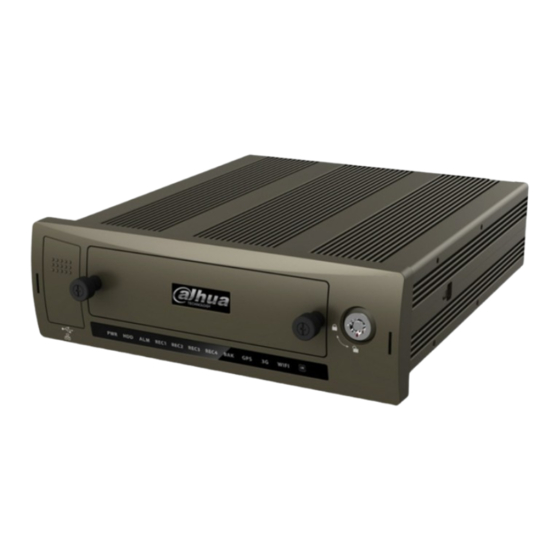
2 Front Panel and Rear Panel 2.1 Front Panel The front panel is shown as in Figure 2-1 when the front door is close. Figure 2-1 Please refer to the following sheet for detailed information. Name Port name and indicator light USB port USB port. -
Page 17: Rear Panel
Name Port name and indicator light of WIFI function supports this function. Remote control receiver It is to receive the signal from the remote control. Device lock/unlock (on/off Please unlock the device before you remove the HDD button) box. Otherwise system is going to shut down automatically. -
Page 18: Extension Port
Name Function Please note only the unit of 3G module supports this function. RJ45 network port Network port 2 Extension port Extension port. Please refer to Figure 2-3 for detailed information. Alarm input/output port Alarm input/output port, GND port, and 12V output. Please refer to chapter 3.6 for detailed information. -
Page 19: Bidirectional Talk Port
2.2.3 Bidirectional talk port The following contents are to introduce function of each port. You can make connection cable by yourself or you can contact your local retailer to purchase. The bidirectional talk port is shown as in Figure 2-4. Figure 2-4 Please refer to the following sheet for detailed information. - Page 20 Figure 2-1 Please refer to the following sheet for detailed information. Serial Number Name Function Power button Click it to boot up or shut down the device. Address Click it to input device number, so that you can control it. Forward Various forward...
-
Page 21: Mouse Operation
playback. In reverse playback click this button to pause playback. Cancel Go back to previous menu or cancel current operation (close upper interface or control) Record Start or stop record manually In record interface, working with the direction buttons to select the record channel. - Page 22 Left click When you have selected one menu item, left click mouse to view menu mouse content. Modify checkbox Click combo box to pop up dropdown list In input box, you can select input methods. Left click the corresponding button on the panel you can input numeral/English character (small/capitalized).
-
Page 23: Installation And Connections
3 Installation and Connections Note: All the installation and operations here should conform to your local electric safety rules. 3.1 Check Unpacked DVR When you receive the DVR from the forwarding agent, please check whether there is any visible damage. The protective materials used for the package of the DVR can protect most accidental clashes during transportation. - Page 24 Figure 3-1 2) Please loosen the screws of the bottom board of the HDD box and then remove the bottom board. Now you can see an interface shown as in Figure 3-2. Figure 3-2 3) Now you can see an interface shown as in Figure 3-3. Use four screws to secure the HDD on the bracket and then use two screws to fasten the bracket on the bottom board.
-
Page 25: Sim Card Installation
Figure 3-3 3.3.2 SIM Card Installation This series product supports built-in SIM card. See Figure 3-4. Remove the HDD box and then open the SIM card slot. Insert the SIM card and then close the cover. Figure 3-4 3.4 Connecting Power Supply Please check input voltage and device power button match or not. -
Page 26: Video Output
The video signal should comply with your national standards. The input video signal shall have high SNR, low distortion; low interference, natural color and suitable lightness. Guarantee the stability and reliability of the camera signal: The camera shall be installed in a cool, dry place away from direct sunlight, inflammable, explosive substances and etc. -
Page 27: Alarm Input And Output Connection
Please refer to Figure 3-6. It is for audio and video output. Figure 3-6 3.6 Alarm Input and Output Connection There are two alarm input types for you to select: normal open (NO) and normal close (NC). 1. Alarm input a. -
Page 28: Alarm Input Port
Figure 3-7 Please refer to the following sheet for detailed information. Name Pin Introduction Alarm input 1~Alarm input 6 1~6 Pulse input 8/10 Alarm GND Controllable 12V NO/C of alarm on-off signal 11/12 3.6.2 Alarm Input Port Please refer to the following sheet for more information. See Figure 3-8. ... - Page 29 Max switch current Max switch power 62.5VA/30W Min allowed load 1mA 5V Mechanical durability 1x10 (300/min) Electric durability 1x10 (30/min) 1000MΩ(500VDC) Performance Insulation resistance Parameter Media Between 1000VAC 1min pressure loop contract Between 400VAC 1min separated contact ≤5ms Operation time (Rated voltage))...
-
Page 30: Operation
4 Operation 4.1 Boot up& Shutdown The buzzer beeps once after system successfully booted up. You can see the corresponding record status indictor light if system is recording after booted up. The system can automatically backup video and resume previous working status after power outage. -
Page 31: Login
4.3 Login You can see login interface. See Figure 4-2. System consists of three accounts. You can refer to chapter 4.10.4 Account for detailed operation information. Username: admin. Password: admin. (administrator, local and network) Username: 888888. Password: 888888. (administrator, local only) ... -
Page 32: Right-Click Menu
Figure 4-3 4.5 Right-Click Menu On the preview interface, right click mouse, you can view menu interface shown as in Figure 4-4. This series product supports 1/4-window mode. Figure 4-4 4.5.1 Window Switch System supports 1/4-window. You can select from the dropdown list. See Figure 4-5. -
Page 33: Ptz Control
Figure 4-5 4.5.2 PTZ Control Before you go to PTZ control interface, please go to chapter 4.9.8 to set PTZ parameter. See Figure 4-6. Figure 4-6 4.5.3 Color Here you can set hue, brightness, contrast, saturation, gain, white level, color mode and etc. See Figure 4-7. -
Page 34: Search
4.5.4 Search Please refer to chapter 4.6. 4.5.5 Record Control Please refer to chapter 4.10.3. 4.5.6 Alarm Output Please refer to chapter 4.10.2. 4.5.7 Device Info Please refer to chapter 4.7.5. 4.5.8 Zero-channel encoding Please refer to chapter 4.9.9. 4.5.9 Main Menu After you logged in, the system main menu is shown as below. - Page 35 Figure 4-9 Please refer to the following sheet for more information. Name Function Display Here is to display the searched picture or file. window For this series product, it supports 1-channel playback. Here you can select to search the picture or the recorded file. ...
- Page 36 channel selection pane. Double click it; you can view the picture/record file list of current day. The file list is to display the first channel of the record file. The system can display max 128 files in one time. Use the / or the mouse ...
-
Page 37: Information
■ Stop Backward play In normal play mode, left click the button, the file begins backward play. Click it again to pause current play. In backward play mode, click ►/ to restore normal play. In playback mode, click it to play the next or the previous section. You can click continuously when you are watching the files from the same channel. -
Page 38: Hdd Information
Figure 4-11 4.7.1 HDD Information Here is to list hard disk type, total space, free space, and status. See Figure 4-12. ○ means current HDD/SD card is normal.. - means there is no HDD. If disk is damaged, system shows as “?”. Please remove the broken hard disk before you add a new one. -
Page 39: Bps
Figure 4-12 Parameter Function SATA 1-2 here means system max supports 2HDDs. When HDD is working properly, system is shown as O. . “_” means there is no HDD. You can view the HDD amount the device connected to; ﹡ means the second HDD is current working HDD. Type The corresponding HDD property. -
Page 40: Log
Figure 4-13 4.7.3 Log Here is for you to view system log file. System lists the following information. See Figure 4-14. Log types include system operation, configuration operation, data management, alarm event, record operation, account management, log clear, file operation and etc. ... -
Page 41: Version
Figure 4-14 Figure 4-15 4.7.4 Version Here is for you to view some version information. See Figure 4-16. System version: Build Date Serial number Model Upgrade Start: Please insert the USB device that have the update file to the device and then click the Start button to begin the update. -
Page 42: Device
Figure 4-17 4.7.5 Device Here you can view some device basic information. It includes ACC status, voltage, record status, HDD status, GPS status, DSS registration status, 3G dial status, WIFI connection status. See Figure 4-18. Figure 4-18 4.7.6 Satellite Info It is to display satellite positioning status and searched results. -
Page 43: Online Users
Figure 4-19 4.7.7 Online Users Here is for you manage WEB online users connected to the local device. See Figure 4-20. You can disconnect one user or block one user if you have proper system right. Figure 4-20 4.7.8 Network Test Network test interface is shown as in Figure 4-21. -
Page 44: Network Load
connection and etc. Network Sniffer backup: Please insert USB2.0 device and click the Refresh button, you can view the device on the following column. You can use the dropdown list to select peripheral device. Click Browse button to select the snap path. The steps here are same as preview backup operation. - Page 45 3G/Wifi/G-sensor/register/maintain/abnormal/TV adjust/speed. Figure 4-23 4.8.1 3G 3G setup interface is shown as below. See Figure 4-24. Please follow the steps listed below to set. a) Boot up 3G module and then check the 3G Enable box to enable this function. b) Please set AUTH, dial number, user name, and password.
-
Page 46: Wifi
APN: It is the wireless connection server. It is to set you access the wireless network via which method. AUTH: It is the authentication mode. It supports PAP/CHAP/ NO AUTH. Dial number: Please input 3G network dialup number you got from your ISP. ... - Page 47 b) In Figure 4-26, click Refresh button to view the entire WIFI signals available. c) Double click a WIFI signal on the list, you can see the WIFI connection dialogue box. d) Select the corresponding verification type. Please contact your network administrator if you do not know how to select the type here.
- Page 48 Figure 4-27 After successfully connection, you can see the following interface. You can see it is connected now. See Figure 4-28. Figure 4-28 After setup, you can click Save button to add it to the hotspot setup list. Besides, you can double click a hotspot on the hotspot real-time list and input password, and then click Save button to save it to the hotspot setup list.
-
Page 49: G-Sensor
On the static setting interface (Figure 4-28), only the hotspot of WEB authentication mode can supports key-index. The hotspot setup list max can save 5 hotspots. The highest priority is 5. The priority shall be unique. System does not support connect to hotspot of OPEN encryption mode. ... -
Page 50: Register
4.8.4 Register This function allows the device to auto register to the proxy you specified. In this way, you can use the client-end to access the DVR and etc via the proxy. Here the proxy has a switch function. In the network service, device supports the server address of IPv4 or domain. -
Page 51: Abnormal
same time, the ACC delay function is null. Figure 4-32 4.8.6 Abnormal Abnormal interface is shown as in Figure 4-33 and Figure 4-34. Event type: There are several options for you such as disk error, no disk, no space, high temperature, low battery, over speed, low speed and etc. -
Page 52: Tv Adjust
Figure 4-33 Figure 4-34 4.8.7 TV Adjust Here is for you to adjust TV output setup. See Figure 4-35. Please drag slide bar to adjust each item. After all the setups please click OK button, system goes b ack to the previous menu. -
Page 53: Speed
Figure 4-35 4.8.8 Speed In this interface, you can view vehicle running kilometers information. See Figure 4-36. Figure 4-36 Setting In main menu, highlight setting icon and double click mouse. System setting interface is shown as below. See Figure 4-37. -
Page 54: General
Figure 4-37 Important Please note you need to have the proper right to implement the following operation. 4.9.1 General General setting includes the following items. See Figure 4-38. System time: Here is for you to set system time Date format: There are three types: YYYYY-MM-DD: MM-DD-YYYYY or DD-MM-YYYY. -
Page 55: Encode
Startup wizard: Once you check the box here, system will go to the startup wizard directly when the system restarts the next time. Otherwise, it will go to the login interface. Note: Since system time is very important, do not modify time casually unless there is a must! Before your time modification, please stop record operation first! After completing all the setups please click save button, system goes back to the previous menu. - Page 56 Type: Please select from the dropdown list. There are two options: regular/alarm. You can set the various encode parameters for different record types. Compression: System supports H.264. Resolution: System supports various resolutions, you can select from the dropdown list. The first two channels support HDCVI 1080P resolution.
- Page 57 Schedule: Click it; you can see an interface shown as in Figure 4-43. Here you can set snapshoot period. Copy:After you complete the setup, you can click Copy button to copy current setup to other channel(s). You can see an interface is shown as in Figure 4-45. You can see current channel number is grey.
-
Page 58: Schedule
Figure 4-43 Figure 4-44 Figure 4-45 4.9.3 Schedule In the main menu, from setting to schedule, you can go to schedule menu. See Figure 4-46. Channel: Please select the channel number first. You can select “all” if you want to set for the whole channels. -
Page 59: Rs232
Redundancy: System supports redundancy backup function. It allows you backup recorded file in two disks. You can highlight Redundancy button to activate this function. Please note, before enable this function, please set at least one HDD as redundant. (Main menu->Advanced->HDD Management). -
Page 60: Network
After completing all the setups please click save button, system goes back to the previous menu. Figure 4-47 4.9.5 Network Here is for you to input network information. See Figure 4-48. IP Version: There are two options: IPv4 and IPv6. Right now, system supports these two IP address format and you can access via them. -
Page 61: Network Setting
Alternate DNS server: DNS server alternate address. Transfer mode: Here you can select the priority between fluency/video qualities. LAN download: System can process the downloaded data first if you enable this function. The download speed is 1.5X or 2.0X of the normal speed. Important For the IP address of IPv6 version, default gateway, preferred DNS and alternate DNS, the input value shall be 128-digit. -
Page 62: Ddns
NTP setup interface is shown as in Figure 4-50. Host IP: Input your PC address. Port: This series DVR supports TCP transmission only. Port default value is 123. Update interval: minimum value is 1. Max value is 65535. (Unit: minute) ... - Page 63 reboot system. Click save button, system prompts for rebooting to get all setup activated. After rebooting, open IE and input the domain name. Now you can open DDNSServer web search page. Figure 4-51 Please note DDNS type includes: CN99 DDNS, NO-IP DDNS, Quick DDNS, and Dyndns DDNS. All the DDNS can be valid at the same time, you can select as you requirement.
-
Page 64: Email
Important Do not register frequently. The interval between two registrations shall be more than 60 seconds. Too many registration requests may result in server attack. System may take back the domain name that is idle for one year. You can get a notification email before the cancel operation if your email address setup is OK. -
Page 65: Ftp
Figure 4-53 4.9.5.5 FTP You need to download or buy FTP service tool (such as Ser-U FTP SERVER) to establish FTP service. Please install Ser-U FTP SERVER first. From “start” -> “program” -> Serv-U FTP Server -> Serv-U Administator. Now you can set user password and FTP folder. Please note you need to grant write right to FTP upload user. -
Page 66: Alarm Center
System also supports upload multiple DVRs to one FTP server. You can create multiple folders under this FTP. In Figure 4-48, select FTP and then double click mouse. You can see the following interface. See Figure 4-56. Please highlight the icon in front of Enable to activate FTP function. -
Page 67: Ethernet Port 2
Figure 4-58 4.9.5.7 Ethernet Port 2 Here you can set Ethernet port 2 information. See Figure 4-59. Figure 4-59 4.9.6 Alarm You can follow the steps listed below to set. You can connect the external alarm port from the rear panel of the device. Usually the vehicle left-turn, right-turn, brake and door signal information and etc can be input to the device via the alarm input device. - Page 68 You need to set for each alarm channel on the Alarm in item if the device has connected several alarm channels. Alarm in: Here is for you to select channel number. Event type: There are two types. Local input/network input alarm. ...
-
Page 69: Detect
Now you can go to the Schedule interface (Main Menu->Setting->Schedule) to set the record type, corresponding channel number, week and date. You can select the recor d type: Regular/Alarm. Now you can go to the Encode interface to select the alarm record and set the encode parameter (Main Menu->Setting->Encode). - Page 70 Select video loss from the dropdown list and select video loss channel. Video loss is shown as below. See Figure 4-62. Event type: From the dropdown list you can select video loss type. Channel: Select a channel from the dropdown list to set video loss function. ...
-
Page 71: Tampering
Figure 4-63 4.9.7.2 Tampering When someone viciously masks the lens, or the output video is in one-color due to the environments light change, the system can alert you to guarantee video continuity. Tampering interface is shown as in Figure 4-64. You can enable alarm output channel and then enable show message function. - Page 72 Decoder A (B) line connects with DVR A (B) line. Boot up the DVR, input user name and password. In the main menu, click setting, and then click Pan/Tilt Control button. The interface is shown as in Figure 4-65. Here you can set the following items: ...
-
Page 73: Display
In Figure 4-66, please click direction arrows to adjust PTZ position. There are total 8 direction arrows. Figure 4-67 Here is a sheet for you reference. Name Function function Shortcut Function function Shortcut Zoom Wide ► │ │ Focus Near ... - Page 74 Figure 4-68 In Figure 4-68, click modify button after channel. You can see an interface shown as in Figure 4-69. Please note all your modification here applies to local end only. You need to refresh web or client-end to get the latest channel name. System max support 25-digital character. Figure 4-69 ...
-
Page 75: Default
Bit Rate: System supports 640/768/896/1024. The bit rate value may vary due to different device capabilities and frame rate setups. Please select from the dropdown list. Save: Click the Save button to save current setup. If this function is disabled, you can not operate zero-channel encoding function at the WEB, the video is black or null even you operate when the function is disabled. -
Page 76: Advanced
Figure 4-71 Warning! System menu color, language, video format, user account cannot restore default setup after default operation! 4.10 Advanced Double click advanced icon in the main window, the interface is shown as below. See Figure 4-72. There are total five items: HDD, alarm output, record, account, and import/export. Figure 4-72 4.10.1 HDD Management Here is for you to view and implement hard disk management. -
Page 77: Alarm Output
Alarm set: Click alarm set button, the interface is shown as below. See Figure 4-74. (This interface is just like the abnormality setup). Please refer to chapter 4.8.6 for detailed information. HDD operation: You can select a HDD mode from the dropdown list such as read-only or you can erase all data in the HDD. -
Page 78: Manual Record
Please highlight icon to select the corresponding alarm output. After all the setups please click OK button, system goes back to the previous menu. See Figure 4-75. Figure 4-75 4.10.3 Manual Record Note: You need to have proper rights to implement the following operations. Please make sure the HDD has been properly installed. -
Page 79: Enable/Disable Record
4.10.3.3 Enable/disable record Please check current channel status: “○” means it is not in recording status, “●” means it is in recording status. You can use mouse or direction key to highlight channel number. See Figure 4-77. Figure 4-77 4.10.3.4 Enable all channel recording Highlight ○... -
Page 80: Stop All Channel Recording
Figure 4-79 4.10.3.5 Stop all channel recording Please highlight “ALL” after “Stop”. See Figure 4-80. System stops all channel recording no matter what mode you have set in the me nu (Main menu->Setting->Schedule) Figure 4-80 4.10.4 Account Here is for you to implement account management. See Figure 4-81. Here you can: ... -
Page 81: Modify Password
Hidden user “default” is for system interior use only and can not be deleted. When there is no login user, hidden user “default” automatically login. You can set some rights such as monitor for this user so that you can view some channel view without login. ... -
Page 82: Add/Modify User
Figure 4-83 4.10.4.3 Add/Modify User Click add user button, the interface is shown as in Figure 4-84. Please input the user name, password, select the group it belongs to from the dropdown list. Then you can check the corresponding rights for current user. For convenient user management, usually we recommend the general user right is lower than the admin account. -
Page 83: Backup
Figure 4-85 4.11 Backup DVR supports USB burner, flash disk, portable HDD, eSATA HDD (Need external power supplying and does not support hot swap). Here we introduce USB backup. You can refer to Chapter 5 Web Operation for network download backup operation. 4.11.1 Detect Device Click backup button, you can see an interface is shown as in Figure 4-86. - Page 84 automatically calculates the capacity needed and remained. See Figure 4-87. Figure 4-87 System only backup files with a √ before channel name. You can use AUX button to check or cancel file. Click backup button, you can backup selected files. There is a process bar for you reference. See Figure 4-88.
-
Page 85: Shutdown
4.12 Shutdown Double click shutdown button, system pops up a dialogue box for you to select. See Figure 4-89. Logout menu user: log out menu. You need to input password when you login the next time. Restart application: reboot device. ... -
Page 86: Web Operation
5 WEB OPERATION There might be slightly difference in the interface due to different series. 5.1 Network Connection Before web operation, please check the following items: Network connection is right DVR and PC network setup is right. Please refer to network setup(Setup ->Network) ... - Page 87 Figure 5-2 After installation, the interface is shown as below. See Figure 5-3. Please input your user name and password. Default factory name is admin and password is admin. Then you can select the login mode: LAN and WAN. Note: For security reasons, please modify your password after you first login. Figure 5-3...
-
Page 88: Lan Mode
5.3 LAN Mode For the LAN mode, after you logged in, you can see the main window. See Figure 5-4. Figure 5-4 This main window can be divided into the following sections. Section 1: there are five function buttons: Live(chapter 5.4), setup (chapter 5.9), search (chapter 5.10), alarm (chapter 5.11), and logout (chapter 5.12). -
Page 89: Real-Time Monitor
Figure 5-7 Section 4: Instant record button. Click it, the button becomes yellow and system begins manual record. See Figure 5-8. Click it again, system restores previous record mode.. Figure 5-8 Section 5: Local play button. The Web can playback the saved (Extension name is dav) files in the PC-end. Click local play button, system pops up the following interface for you to select local play file. -
Page 90: Ptz
Figure 5-10 On the top right corer, there are six unction buttons. See Figure 5-11. Figure 5-11 1: Digital zoom: Click this button and then left drag the mouse in the zone to zoom in. right click mouse system restores original status. ... -
Page 91: Image/Relay-Out
Parameter Function Select Tour from the dropdown list. Tour Input preset value in the column. Click Add preset button, you have added one preset in the tour. Repeat the above procedures you can add more presets in one tour. -
Page 92: Relay Output
Figure 5-13 5.6.2 Relay output Here you can select alarm output channel, the select channel alarm mode becomes manual when the alarm is enabled. See Figure 5-14. It is corresponding to the alarm output 1/2 of the rear panel. Please refer to chapter 3.6.1 for detailed information. Figure 5-14 5.7 Zero-channel encoding System allows you to preview several channels on one channel. -
Page 93: Setup
Figure 5-16 Please refer to the following contents for LAN and WAN login difference. 1) In the WAN mode, system opens the main stream of the first channel to monitor by default. The open/close button on the left pane is null. 2) You can select different channel and different monitor mode at the bottom of the interface. - Page 94 Figure 5-17 Please refer to the following sheet for detailed information. Parameter Function Channel Please select a channel from the dropdown list. Period It divides one day (24 hours) to two periods. You can set different hue, brightness, and contrast for different periods. It is to adjust monitor video brightness and darkness level.
-
Page 95: Video And Audio
attractive if the value is too low. The recommended value ranges from 40 to 60. Gain The gain adjust is to set the gain value. The smaller the value is, the low the noise is. But the brightness is also too low in the dark environments. -
Page 96: Snapshot
System supports various resolutions, you can select from Resolution the dropdown list. The first two channels support HDCVI 1080P resolution. The last two channels support HDCVI 720P resolution. System default setup is HDCVI 720P. Please make sure you are connecting to the HDCVI 1080P camera if you want to realize 720P/1080P resolution. -
Page 97: Overlay
Parameter Function There are two modes: Timing (schedule) and Event (activation). Snapshot type Timing snapshot is valid during the specified period you set. Activation snapshot only is valid when tampering alarm or local activation alarm occurs. Image size It is the same with the resolution of the main stream. -
Page 98: Zero-Ch Encoding
Channel Title You can enable this function so that system overlays channel information in video window. You can use the mouse to drag the channel title position. You can view channel title on the live video of the WEB or the playback video. -
Page 99: Path
Figure 5-22 5.9.1.2.6 Path The storage path interface is shown as in Figure 5-23. Here you can set snap image saved path and the record storage path. The default setup is C:\PictureDownload and C:\RecordDownload. Please click the Save button to save current setup. Figure 5-23 5.9.1.3 Channel Name Here you can set channel name. -
Page 100: Network
Figure 5-24 5.9.2 Network 5.9.2.1 TCP/IP The TCP/IP interface is shown as in Figure 5-25. Figure 5-25 Please refer to the following sheet for detailed information. Parameter Function Mode There are two modes: static mode and the DHCP mode. The IP/submask/gateway are null when you select the DHCP mode to auto search the IP. -
Page 101: Connection
For the IP address of IPv6 version, default gateway, preferred DNS and alternate DNS, the input value shall be 128-digit. It shall not be left in blank. System can process the downloaded data first if you enable this LAN load function. - Page 102 Figure 5-27 Please refer to the following sheet for detailed information. Parameter Function Server Type You can select DDNS protocol from the dropdown list and then enable DDNS function. Server IP DDNS server IP address Server Port DDNS server port. Domain Name Your self-defined domain name.
-
Page 103: Email
Except default domain name registration, you can also use customized domain name (You can input your self-defined domain name.) After successful registration, you can use domain name to login installed of the device IP. User name: It is optional. You can input your commonly used email address. Important ... -
Page 104: Alarm Centre
Parameter Function Input email subject here. Subject System can send out the email of the snapshot picture once Attachment you check the box here. Input receiver email address here. Max three addresses. Receiver It supports SSL, TLS email box. The send interval ranges from 0 to 3600 seconds. 0 means Interval there is no interval. -
Page 105: Event
Please refer to the following sheet for detailed information. Parameter Function Server IP Alarm centre IP address. Port Alarm centre port value. Self-report time System auto report current alarm status at the specified time. Event 5.9.3 5.9.3.1 Video detect 5.9.3.1.1 Video loss The video loss interface is shown as in Figure 5-30. -
Page 106: Tampering
Parameter Function Schedule to set current channel as schedule record. Record Delay System can delay the record for specified time after alarm ended. The value ranges from 10s to 300s. Alarm out Enable alarm activation function. You need to select alarm output port so that system can activate corresponding alarm device when an alarm occurs. -
Page 107: Local Alarm
5.9.3.2.1 Local Alarm The local alarm interface is shown as in Figure 5-33. Figure 5-33 Figure 5-34 Please refer to the following sheet for detailed information. Parameter Function Enable You need to check the box to enable this function. Please select a channel from the dropdown list. Period This function becomes activated in the specified periods. -
Page 108: Net Alarm
Parameter Function High/low. Please highlight the box here to enable this function. It can Overlay overlay alarm information on the video screen when an alarm occurred. Anti-dither System only memorizes one event during the anti-dither period. The value ranges from 5s to 600s. Record channel System auto activates channel(s) to record once an alarm occurs. -
Page 109: Alarm Out
Figure 5-35 5.9.3.2.3 Alarm Out Here you can set alarm output channel mode: schedule/manual/stop. See Figure 5-36. Figure 5-36 5.9.4 Storage 5.9.4.1 Schedule In this interfaces, you can add or remove the schedule record setup. See Figure 5-37. There are three record modes: general (auto) and alarm. There are six periods in one day. Please make sure you have enabled the corresponding record mode in the Setup->Storage->Conditions. - Page 110 Figure 5-37 Figure 5-38 Figure 5-39 Please refer to the following sheet for detailed information. Parameter Function Channel Please select a channel from the dropdown list.
-
Page 111: Storage
Parameter Function Pre-record Please input pre-record time here. The value ranges from 0 to 30. Redundancy Check the box here to enable redundancy function. Please note this function is null if there is only one HDD. Snapshot Check the box here to enable snapshot function. Holiday Check the box here to enable holiday function. -
Page 112: Record Control
The FTP function is on if you check the Enable box here. When network is offline or malfunction, system can save record or picture to HDD. Figure 5-41 5.9.4.3 Record control The record control interface is shown as in Figure 5-42. Figure 5-42 Please refer to the following sheet for detailed information. -
Page 113: System
It has the highest priority. Manual Enable corresponding channel to record no matter what period applied in the record setup. Stop current channel record no matter what period applied in the Stop record setup. Check the corresponding All button, you can enable or disable all Start all/ stop all channels record. -
Page 114: Account
The date and time interface is shown as in Figure 5-44 Figure 5-44 Please refer to the following sheet for detailed information. Parameter Function Here you can select date format from the dropdown list. Date format There are two options: 24-H and 12-H. Time Format The time zone of the device. -
Page 115: User Name
User management adopts group/user modes. The user name and the group name shall be unique. One user shall be included in only one group. 5.9.5.2.1 User name In this interface you can add/remove user and modify user name. See Figure 5-45. Figure 5-45 Add user: It is to add a name to group and set the user rights. -
Page 116: Group
Modify user It is to modify the user property, belonging group, password and rights. See Figure 5-47. Modify password It is to modify the user password. You need to input the old password and then input the new password twice to confirm the new setup. Please click the OK button to save. Please note, the password ranges from 1-digit to 6-digit. -
Page 117: Default
Figure 5-49 Modify group Click the modify group button, you can see an interface is shown as in Figure 5-50. Here you can modify group information such as remarks and rights. Figure 5-50 5.9.5.3 Default The default setup interface is shown as in Figure 5-51. Here you can select Channel/Network/Event/Storage/System. -
Page 118: Import/Export
5.9.5.4 Import/Export The interface is shown as in Figure 5-52. Figure 5-52 Please refer to the following sheet for detailed information. Parameter Function It is to import the local setup files to the system. Import It is to export the corresponding WEB setup to your local PC. Export 5.9.5.5 Upgrade The upgrade interface is shown as in Figure 5-53. -
Page 119: Ptz
Figure 5-54 Please refer to the following sheet for detailed information. Parameter Function Select the corresponding COM control protocol. Function Default setup is console. Select the baud rate. Baud Rate Default setup is 115200. Data Bit The value ranges from 5 to 8. Default setup is 8. -
Page 120: Information
Please refer to the following sheet for detailed information. Parameter Function Select speed dome connected channel. Channel Select the corresponding dome protocol such as PELCOD. Protocol Set corresponding dome address. Default value is 1. Please note Address your setup here shall comply with your dome address; otherwise you can not control the speed dome. -
Page 121: Vehicle
Figure 5-57 Please refer to the following sheet for log parameter information. Parameter Function Log types include: system operation, configuration operation, data Type operation, event operation, record operation, user management, log clear. Set the start time of the requested log. Start time Set the end time of the requested log. -
Page 122: Wifi
Figure 5-58 5.9.7.2 WIFI Please note this function is for the device of WIFI module. The WIFI interface is shown as in Figure 5-59. Please refer to chapter 4.8.2 for detailed setup information. Figure 5-59 Please check the box to enable WIFI function and then click the Search SSID button. Now you can view all the wireless network information in the following list. -
Page 123: Cdma/Gprs
5.9.7.3.1 CDMA/GPRS The CDMA/GPRS interface is shown as in Figure 5-60. Figure 5-60 Please refer to the following sheet for detailed information. Parameter Function WLAN type Here you can select 3G network type to distinguish the 3G module from different ISP. The types include WCDMA, CDMA1x and etc. -
Page 124: Auto Register
Figure 5-61 5.9.7.4 Auto Register The auto register interface is shown as in Figure 5-62. After the device connects to the network, it can send out auto register query to the specified server. Figure 5-62 Please refer to the following sheet for detailed information. Parameter Function Server IP... -
Page 125: Abnormality
Figure 5-63 5.9.7.6 Abnormality It includes six statuses: No disk, disk error, disk no space, battery low, temperature high. See Figure 5-64 through Figure 5-68. Figure 5-64 Figure 5-65... - Page 126 Figure 5-66 Figure 5-67 Figure 5-68 Please refer to the following sheet for detailed information.
-
Page 127: Display
Parameter Function Event The abnormal events include: No disk, disk error, disk no space, battery Type low, temperature high. You can set one or more items here. Enable Check the box here to enable selected function. Alarm Out Please select corresponding alarm output channel when an alarm occurs. -
Page 128: Tv Adjust
Check the box here, you can view system time and channel Time title/channel number on the monitor video. title Check the box; you can optimize the margin of the preview video. Image enhance Here is for you to set auto logout interval once login user remains Auto logout inactive for a specified time. -
Page 129: Playback
Figure 5-71 5.10 Playback Click Playback button, you can see an interface is shown as in Figure 5-72. Please set record type, record date, window display mode and channel name. You can click the date on the right pane to select the date. The green highlighted date is system current date and the blue highlighted date means it has record files. -
Page 130: Playback Record
bar, system begins playback. The time bar is beginning with 0 o'clock when you are setting the configuration. The time bar zooms in the period of the current playback time when you are playing the file. The green color stands for the regular record file. The red color stands for the alarm record file. -
Page 131: File List
5.10.3 File List Then please click file list button (Button 6 in Figure 5-72 ), you can see the corresponding files in the list. See Figure 5-74. Figure 5-74 Description Please select a date on the calendar pane and then input time here to search records of the specified time. - Page 132 Description setting record channel, record type and record time. Here you can also download file to your local PC or USB devices. You can go to chapter 5.9.1.2.6 to set download path. Load more It is for you to search record or picture. You can select record channel, record type and record time to download.
-
Page 133: Alarm
Figure 5-77 5.11 Alarm Click alarm function, you can see an interface is shown as Figure 5-78. Here you can set device alarm type and alarm sound setup. Figure 5-78 Please refer to the following sheet for detailed information. Please make sure current device can upload the alarm. Type Parameter Function... -
Page 134: Log Out
Type Parameter Function Operation Prompt Check the box here, system can automatically pops up an alarm icon on the Alarm button in the main interface when there is an alarm. Alarm Play alarm sound System sends out alarm sound when an alarm Sound occurs. -
Page 135: Digital Surveillance System
6 Digital Surveillance System Besides Web, you can use our Digital Surveillance Software (DSS) to login the device. For detailed information, please refer to DSS user’s manual. - Page 136 7 FAQ 1. After the vehicle started, the DVR can not boot up properly. There are following possibilities: Input power is not correct. It is too high or too low. Power connection is not correct. Power switch button is damaged. ...
- Page 137 Video transmission is too long or degrading is too huge. DVR color or brightness setup is not correct. 6. Can not search local records. There are following possibilities: HDD ribbon is damaged. HDD is broken. Upgraded program is not compatible.
- Page 138 PTZ decoder and DVR protocol is not compatible. PTZ decoder and DVR address is not compatible. When there are several decoders, please add 120 Ohm between the PTZ decoder A/B cables furthest end to delete the reverberation or impedance matching. Otherwise the PTZ control is not stable.
- Page 139 There are following possibilities: Alarm setup is not correct. Alarm output has been open manually. Input device error or connection is not correct. Some program versions may have this problem. Please upgrade your system. 17. Alarm function is null. There are following possibilities: ...
- Page 140 Check local auto register function setup. Check server setup. 23. No GPS data There are following possibilities: Check GPS antenna connection GPS antenna environment is free of block object. Vehicle data module is running or not. Daily Maintenance ...
- Page 141 Appendix A HDD Capacity Calculation Calculate total capacity needed by each device according to video recording (video recording type and video file storage time). Step 1: According to Formula (1) to calculate storage capacity that is the capacity of each channel needed for each hour, unit Mbyte.
- Page 142 If there is any uncertainty or controversy, please refer to the final explanation of us. Please visit our website or contact your local service engineer for more information.
Need help?
Do you have a question about the MCVR5104-GCW and is the answer not in the manual?
Questions and answers