Table of Contents
Advertisement
Quick Links
This equipment has been tested and found to comply with the limits of a Class B digital device,
pursuant to Part 15 of the FCC Rules. These limits are designed to provide reasonable protection
against harmful interference in a residential installation. This equipment generates, uses, and can
radiate radio frequency energy and, if not installed and used in accordance with the instructions,
may cause harmful interference to radio communications. There is no guarantee that interference
will not occur in a particular installation.
The vendor makes no representations or warranties with respect to the contents here and
specially disclaims any implied warranties of merchantability or fitness for any purpose. Further
the vendor reserves the right to revise this publication and to make changes to the contents here
without obligation to notify any party beforehand.
Duplication of this publication, in part or in whole, is not allowed without first obtaining the
vendor's approval in writing.
The content of this user's manual is subject to be changed without notice and we will not be
responsible for any mistakes found in this user's manual. All the brand and product names are
trademarks of their respective companies.
FCC Information and Copyright
Dichiarazione di conformità sintetica
Ai sensi dell'art. 2 comma 3 del D.M. 275 del
30/10/2002
Si dichiara che questo prodotto è conforme
alle normative vigenti e soddisfa i requisiti
essenziali richiesti dalle direttive
2004/108/CE, 2006/95/CE e 1999/05/CE
quando ad esso applicabili
Short Declaration of conformity
We declare this product is complying with the
laws in force and meeting all the essential
requirements as specified by the directives
2004/108/CE, 2006/95/CE and 1999/05/CE
whenever these laws may be applied
Advertisement
Table of Contents

Subscribe to Our Youtube Channel
Related Manuals for Biostar J4105NHU


Summary of Contents for Biostar J4105NHU
-
Page 1: Fcc Information And Copyright
FCC Information and Copyright This equipment has been tested and found to comply with the limits of a Class B digital device, pursuant to Part 15 of the FCC Rules. These limits are designed to provide reasonable protection against harmful interference in a residential installation. This equipment generates, uses, and can radiate radio frequency energy and, if not installed and used in accordance with the instructions, may cause harmful interference to radio communications. -
Page 2: Table Of Contents
Table Of Contents FCC Information and Copyright ������������������������������������������������������������������������������� 1 Chapter 1: Introduction ������������������������������������������������������������������������������������������� 3 1.1 Before You Start ........................3 1.2 Package Checklist ........................ 3 1.3 Specifications ........................4 1.4 Rear Panel Connectors ......................5 1.5 Motherboard Layout ......................6 Chapter 2: Hardware installation �����������������������������������������������������������������������������... -
Page 3: Chapter 1: Introduction
J4105NHU Chapter 1: Introduction 1�1 Before You Start Thank you for choosing our product. Before you start installing the motherboard, please make sure you follow the instructions below: • Prepare a dry and stable working environment with sufficient lighting. • Always disconnect the computer from power outlet before operation. -
Page 4: Specifications
1x TPM Header (Optional) Form Factor Mini-ITX Form Factor, 170 mm x 170 mm Windows 10(64bit) OS Support * Biostar reserves the right to add or remove support for any OS with or without notice. 4 | Chapter 1: Introduction... -
Page 5: Rear Panel Connectors
J4105NHU 1�4 Rear Panel Connectors Note » VGA, HDMI ports only work with an Intel® integrated Graphics Processor. » Maximum resolution VGA: 1920 x 1200 @60Hz HDMI: 4096x 2160 @30Hz, compliant with HDMI 1.4 » When using the front HD audio jack and plug in the headset, the rear sound will be automatically Disabled. » The mainboard supports two onboard display outputs at same time and the display output configuration can be selected in Intel graphics driver utility. The 2/ 4/ 5.1/ 7.1-channel configuration Audio Port 2-channel 4-channel 5.1 channel 7.1 channel Blue (Rear Panel) Line In Line In... -
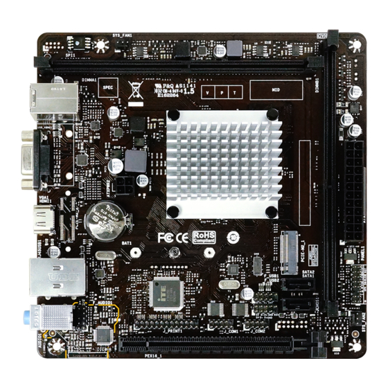
Page 6: Motherboard Layout
1.5 Motherboard Layout Note » represents the 1st pin. » The PCIE-M2_2 slot/ TPM header is optional. 6 | Chapter 1: Introduction... -
Page 7: Chapter 2: Hardware Installation
J4105NHU Chapter 2: Hardware installation 2.1 Connect Cooling Fans These fan headers support cooling-fans built in the computer. The fan cable and connector may be different according to the fan manufacturer. SYS_FAN1/2: System Fan Header Pin Assignment Ground +12V FAN RPM rate sense Note » SYS_FAN1/2 support 3-pin head connectors. When connecting with wires onto connectors, please... - Page 8 Step 1: Unlock a DIMM slot by pressing the retaining clips outward. Align a DIMM on the slot such that the notch on the DIMM matches the break on the slot. Step 2: Insert the DIMM vertically and firmly into the slot until the retaining clips snap back in place and the DIMM is properly seated.
-
Page 9: Expansion Slots
J4105NHU 2.3 Expansion Slots PEX16_1: PCI-Express Gen2 x16 Slot • PCI-Express 2.0 compliant. • Maximum theoretical realized bandwidth of 8GB/s simultaneously per direction, for an aggregate of 16GB/s totally. PCIE-M2_1: M.2 (Key M) Slot • The M.2 slot supports M.2 Type 2242/2260/2280 SSD module. When installing M.2 SSD module, please place the screw and hex pillar to correct position. -
Page 10: Jumper & Switch Setting
2.4 Jumper & Switch Setting The illustration shows how to set up jumpers. When the jumper cap is placed on pins, the jumper is “close”, if not, that means the jumper is “open”. Pin opened Pin closed Pin 1-2 closed JCMOS1: Clear CMOS Jumper The jumper allows users to restore the BIOS safe setting and the CMOS data. -
Page 11: Headers & Connectors
J4105NHU 2.5 Headers & Connectors ATXPWR1: ATX Power Source Connector For better compatibility, we recommend to use a standard ATX 24-pin power supply for this connector. Make sure to find the correct orientation before plugging the connector. Assignment Assignment +3.3V +3.3V... - Page 12 TPM1: Trusted Platform Module Header (Optional) This header allows you to store cryptographic keys that protect information. Assignment Pin Assignment F_LAD0 F_LAD1 F_LAD2 C_PCICLK_TPM F_LAD3 F_FRAME# 10 NC F_SERIRQ 12 S_PCIRST#_TBD F_CLKRUN 14 +3VSB SATA1/2: Serial ATA Connectors These connectors connect to SATA hard disk drives via SATA cables. Assignment Ground Ground...
- Page 13 J4105NHU F_AUDIO1: Front Panel Audio Header This header allows user to connect the chassis-mount front panel audio I/O which supports HD and AC’97 audio standards. HD Audio AC’97 Assignment Pin Assignment Mic Left in Mic In Ground Ground Mic Right in...
-
Page 14: Chapter 3: Uefi Bios & Software
The BIOS can be updated using either of the following utilities: • BIOSTAR BIOS-FLASHER: Using this utility, the BIOS can be updated from a file on a hard disk, a USB drive (a flash drive or a USB hard drive), or a CD-ROM. - Page 15 J4105NHU 6. Select the proper BIOS file, and a message asking if you are sure to flash the BIOS file. Click “Yes” to start updating BIOS. 7. A dialog pops out after BIOS flash is completed, asking you to restart the system. Press the <Y> key to restart system.
- Page 16 Then, the BIOS Update is completed. BIOS Update Utility (through a BIOS file) 1. Installing BIOS Update Utility from the DVD Driver. 2. Download the proper BIOS from http://www.biostar.com.tw/ 3. Launch BIOS Update Utility and click the “Update BIOS” button on the main screen.
- Page 17 J4105NHU 5. Choose the location for your BIOS file in the system. Please select the proper BIOS file, and then click on “Open”. It will take several minutes, please be patient. 6. After the BIOS Update process is finished, click on “OK”...
-
Page 18: Chapter 4: Useful Help
Chapter 4: Useful help 4�1 Driver Installation After you installed your operating system, please insert the Fully Setup Driver DVD into your optical drive and install the driver for better system performance. You will see the following window after you insert the DVD The setup guide will auto detect your motherboard and operating system. -
Page 19: Ami Bios Beep Code
J4105NHU 4.2 AMI BIOS Beep Code Boot Block Beep Codes Number of Beeps Description Continuing Memory sizing error or Memory module not found POST BIOS Beep Codes Number of Beeps Description Success booting. Display memory error (system video adapter) 4�3 AMI BIOS post code... - Page 20 Code Description South Bridge DXE initialization is started South Bridge DXE SMM initialization is started South Bridge devices initialization South Bridge DXE Initialization (South Bridge module specific) ACPI module initialization Boot Device Selection (BDS) phase is started Driver connecting is started PCI Bus initialization is started PCI Bus Hot Plug Controller Initialization PCI Bus Enumeration...
-
Page 21: Troubleshooting
J4105NHU 4�4 Troubleshooting Probable Solution 1. There is no power in the system. Power LED does 1. Make sure power cable is securely plugged in. not shine; the fan of the power supply does not work 2. Replace cable. 2. Indicator light on keyboard does not shine. -
Page 22: Appendix I: Specifications In Other Languages
APPENDIX I: Specifications in Other Languages Arabic 22 | APPENDIX I: Specifications in Other Languages... -
Page 23: German
1x Header für klares CMOS 1x TPM-Header (wahlweise) Formfaktor Mini-ITX Formfaktor, 170 mm x 170 mm Windows 10(64bit) OS-Unterstützung * Biostar reserves the right to add or remove support for any OS with or without notice. APPENDIX I: Specifications in Other Languages | 23... -
Page 24: Russian
1 контакт микросхемы Clear CMOS 1 контакт TPM (необязательный) Конструктив Форм-фактор Mini-ITX, 170мм x 170 мм Windows 10(64bit) Поддержка ОС * Biostar оставляет за собой право добавлять или удалять поддержку любой ОС, с уведомлением или без. 24 | APPENDIX I: Specifications in Other Languages... -
Page 25: Spanish
Factor de Forma Factor de Forma Mini-ITX, 170 mm x 170 mm Windows 10(64bit) Soporte OS * Biostar reserva su derecho de añadir o retirar el soporte para cada OS con o sin notificación. APPENDIX I: Specifications in Other Languages | 25... -
Page 26: Thai
สนั บ สนุ น OS Biostar ขอสงวนสิ ท ธิ ์ ใ นการเพิ ่ ม หรื อ ถอดการสนั บ สนุ น สำ า หรั บ ระบบปฏิ บ ั ต ิ ก าร OS ต่ า งๆ โดยไม่ ต ้ อ งแจ้ ง ให้ ท ราบล่ ว งหน้ า... - Page 27 J4105NHU this page intentionally left blank APPENDIX I: Specifications in Other Languages | 27...
Need help?
Do you have a question about the J4105NHU and is the answer not in the manual?
Questions and answers