HP Compaq Evo N1010v Series Service Manual
Hp evo n1010v: service manual
Hide thumbs
Also See for Compaq Evo N1010v Series:
- Service manual (188 pages) ,
- Startup manual (75 pages) ,
- Limited warranty (64 pages)
Table of Contents
Advertisement
HP Pavilion ze5600 Notebook PC
HP Pavilion ze5500 Notebook PC
HP Pavilion ze5400 Notebook PC
HP Pavilion ze5300 Notebook PC
HP Pavilion ze5200 Notebook PC
HP Pavilion ze4700 Notebook PC
HP Pavilion ze4600 Notebook PC
HP Pavilion ze4500 Notebook PC
HP Pavilion ze4400 Notebook PC
HP Pavilion ze4300 Notebook PC
HP Pavilion ze4200 Notebook PC
HP Pavilion ze4100 Notebook PC
HP Compaq nx9010 Notebook PC
HP Compaq nx9008 Notebook PC
HP Compaq nx9005 Notebook PC
HP Compaq nx9000 Notebook PC
Compaq Evo Notebook N1050v Series
Compaq Evo Notebook N1010v Series
Compaq Presario 2500 Series Mobile PC
Compaq Presario 2100 Series Mobile PC
Compaq Presario 1100 Series Mobile PC
(All Models use technology code KE)
Service Manual
Advertisement
Table of Contents
Troubleshooting

Related Manuals for HP Compaq Evo N1010v Series


Summary of Contents for HP Compaq Evo N1010v Series
-
Page 1: Service Manual
HP Pavilion ze5600 Notebook PC HP Pavilion ze5500 Notebook PC HP Pavilion ze5400 Notebook PC HP Pavilion ze5300 Notebook PC HP Pavilion ze5200 Notebook PC HP Pavilion ze4700 Notebook PC HP Pavilion ze4600 Notebook PC HP Pavilion ze4500 Notebook PC... - Page 2 The information contained herein is subject to change without notice. The only warranties for HP products and services are set forth in the express warranty statements accompanying such products and services. Nothing herein should be construed as constituting an additional warranty. HP shall not be liable for technical or editorial errors or omissions contained herein.
-
Page 3: Table Of Contents
Contents Introduction... vii Product Information... 1-1 Features ... 1-8 Operation... 1-14 Specifications ... 1-18 Internal Design... 1-24 Removal and Replacement... 2-1 Disassembly Flowchart ... 2-3 Removing the Battery ... 2-4 Removing an SDRAM Module... 2-5 Removing the Wireless LAN Mini PCI Card ... 2-7 Removing the Hard Disk Drive... - Page 4 Figures Figure 1-1. Front View... 1-8 Figure 1-2. Back View ... 1-9 Figure 1-3. Bottom View... 1-10 Figure 1-4. Front View... 1-11 Figure 1-5. Back View ... 1-12 Figure 1-6. Bottom View... 1-13 Figure 1-7. Resetting the Notebook ... 1-17 Figure 1-8.
- Page 5 Figure 2-36. Disconnecting the Motherboard Cables ... 2-54 Figure 2-37. Removing the Motherboard... 2-56 Figure 2-38. Example of Serial Number Label ... 2-59 Figure 2-39. Replacing the Antennas... 2-60 Figure 2-37. Removing a PCMCIA Door ... 2-60 Figure 2-38. Boot-Block Jumper... 2-62 Figure 3-1.
-
Page 6: Introduction
Introduction This manual provides reference information for servicing the HP Pavilion ze5600, ze5500, ze5400, ze5300, ze5200, ze4700, ze4600, ze4500, ze4400, ze4300, ze4200, and ze4100 Notebook PCs, HP Compaq nx9010, nx9008, nx9005, and nx9000 Notebook PCs, Compaq Evo Notebook 1050v and 1010v Series, and Compaq Presario 2500, 2100, and 1100 Series Mobile PCs. These notebook models use technology code KE. -
Page 7: Product Information
The following list of HP and Compaq notebook products is current at the time of publication but is subject to change. HP Pavilion ze5600 Processor Intel® Celeron® (2.6-, 2.8-GHz) Mobile Intel Pentium® 4 (2.4-, 2.66-, 2.8-, and 3.06-GHz) Memory Up to 1 GB (1024 MB) SDRAM using 512-MB modules. At least 256 MB SDRAM preinstalled. - Page 8 HP Pavilion ze5400 and ze5300 Processor Mobile Intel Pentium 4 (2.4-, 2.66-, 2.8-, and 3.06-GHz) Memory Up to 1 GB (1024 MB) SDRAM using 512-MB modules. At least 256 MB SDRAM preinstalled. Display 15.0-inch XGA (1024 × 768) or SXGA+ (1400 × 1050) or 14.1-inch XGA (1024 ×...
- Page 9 HP Pavilion ze4600 Processor AMD Athlon (1.47-, 1.53-, 1.67-, 1.8-, 2.2-, and 2.08-GHz) Memory Up to 1 GB (1024 MB) SDRAM using 512-MB modules. At least 128 MB SDRAM preinstalled. Display 15.0-inch XGA (1024 × 768) or SXGA+ (1400 × 1050) or 14.1-inch XGA (1024 ×...
- Page 10 HP Pavilion ze4300 Processor Mobile Intel Pentium 4-M (1.8-, 2.0-, 2.2-, and 2.4-GHz) Intel Celeron (1.8-, 2.0-, and 2.2-GHz) AMD Athlon (1.47-, 1.53-, 1.67-, 1.8-, Memory Up to 1 GB (1024 MB) SDRAM using 512-MB modules. At least 128 MB SDRAM preinstalled.
- Page 11 HP Compaq nx9010 Processor Mobile Intel Pentium 4 (2.4-, 2.53-, 2.66-, and 3.06-GHz) Intel Celeron (2.0- and 2.6-GHz) Memory Up to 1 GB (1024 MB) SDRAM using 512-MB modules. At least 256 MB SDRAM preinstalled. Display 15.0-inch XGA (1024 × 768) or SXGA+ (1400 × 1050) active-matrix TFT...
- Page 12 HP Compaq nx9000 Processor AMD Athlon (1.8- or 2.0-GHz) Memory Up to 1 GB (1024 MB) SDRAM using 512-MB modules. At least 256 MB SDRAM preinstalled. Display 15.0-inch XGA (1024 × 768) or SXGA+ (1400 × 1050) active-matrix TFT Video...
- Page 13 Compaq Presario 2500 Processor Mobile Intel Pentium 4 (2.0-, 2.3-, 2.4-, 2.53-, 2.66-, 2.8-, and 3.06-GHz) Intel Celeron (2.6- and 2.8-GHz) Memory Up to 1 GB (1024 MB) SDRAM using 512-MB modules. At least 256 MB SDRAM preinstalled. Display 15.0-inch XGA (1024 × 768) or SXGA+ (1400 × 1050) or 14.1-inch XGA (1024 ×...
-
Page 14: Features
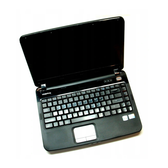
Features The following illustrations show the notebook’s main external features. For an exploded view of the notebook, see page 4-2. HP Pavilion ze4x00, HP Compaq nx9005 and nx9000, Compaq Evo Notebook N1050v and N1010v, Notebook open/close latch One-touch buttons Keyboard status lights... -
Page 15: Figure 1-2. Back View
20. Kensington lock slot (security connector) Service Manual Figure 1-2. Back View HP Pavilion ze4x00 HP Compaq nx9005 and nx9000 21. Modem port* 22. PCMCIA card and CardBus slot and button 23. IEEE 1394 port* 24. Audio jacks (left to right), external microphone and audio out (headphones) 25. -
Page 16: Figure 1-3. Bottom View
HP Pavilion ze4x00, HP Compaq nx9005 and nx9000, Compaq Evo Notebook N1050v and N1010v, 28. Hard disk drive 29. Battery latch 30. SDRAM door 1-10 Product Information Figure 1-3. Bottom View and Compaq Presario 2100 and 1100 31. Reset button 32. -
Page 17: Figure 1-4. Front View
Infrared port* Service Manual Figure 1-4. Front View HP Pavilion ze5x00, HP Compaq nx9010 and nx9008, and Compaq Presario 2500 Wireless on-off button and indicator light* Audio mute button and audio mute light* 10. Battery 11. -
Page 18: Figure 1-5. Back View
20. External monitor port 1-12 Product Information Figure 1-5. Back View HP Pavilion 5x00, HP Compaq nx9010, and nx9008 and Compaq Presario 2500 21. S-Video port* 22. Kensington lock cable slot (security connector) 23. Modem port* 24. IEEE 1394 port* 25. -
Page 19: Figure 1-6. Bottom View
29. Mini PCI door (no user parts inside) 30. SDRAM door Service Manual Figure 1-6. Bottom View HP Pavilion 5x00, HP Compaq nx9010,and nx9008, and Compaq Presario 2500 31. Port replicator connect* 32. Reset button * on certain models Product Information... -
Page 20: Operation
Operation This section gives an overview of the notebook’s operation. Turning the Notebook On and Off You can start and stop your notebook using its power button. However, at certain times you might want to use other methods to start or stop the notebook—depending on power considerations, types of active connections, and start-up time. -
Page 21: Table 1-3. Main Status Lights (Front Of Notebook)
Checking the Status of the Notebook The main status lights on the front of the notebook report power status, battery status, and hard disk activity. Table 1-3. Main Status Lights (front of notebook) Meaning Power status On: notebook is on (even if the display is off). Blinking: notebook is in Standby mode. -
Page 22: Table 1-5. Fn Hot Keys
Using Fn Hot Keys The combination of the key plus another key creates a hot key—a shortcut key sequence—for various system controls. To use a hot key, press and hold then release both keys. Hot Key Effect Decreases the display brightness Fn+F1 Increases the display brightness Fn+F2... -
Page 23: Figure 1-7. Resetting The Notebook
NOTE: To boot from a CD, insert a bootable CD (such as the Recovery CDs) into the CD/DVD drive, then restart. Press when the HP logo appears, and then select the CD/DVD drive as the temporary boot device. Service Manual and then select Shut Down >... -
Page 24: Specifications
The following tables list the specifications for the notebook and its accessories and are subject to change. For the latest versions, see the HP Notebook Web site Size (14-inch display): 328 × 272 × 33 mm (12.9 × 10.7 × 1.3 in) Physical Attributes Size (15-inch display): 328 ×... - Page 25 Processor and Bus Compaq Evo Notebook N1050v: Architecture 1.8-GHz Mobile Intel Pentium 4 Processor-M with Intel Speed Step technology, (continued) 512-KBL2 cache, and 1.2- to 1.3-V core low-power processor with 400-MHz processor system bus -or- 1.6-GHz Intel Celeron processor with 256-KB L2 cache and 1.45-V core low-power processor with 133-MHz processor system bus Compaq Evo Notebook N1010v: 1.6-GHz Intel Celeron processor with 256-KB L2 cache and 1.45-V core low-power...
- Page 26 1.44-MB floppy drive (certain models) 24x CD-ROM, 8x DVD, CD-RW, or CD-RW/DVD drive (or higher) At least 128 MB SDRAM preinstalled HP Pavilion ze5x00, ze4x00, HP Compaq nx9010, nx9008, nx9005, Compaq Evo N1050v, Compaq Presario 2500, and Compaq Presario 2100:...
-
Page 27: Table 1-7. Accessories
Accessory Description Memory F4694-60901 128MB DDR266B 317434-001 F4695-60901 256MB DDR266B 317435-001 F4696-60901 512MB DDR266B 317436-001 Hard Drives 0950-4193 HDD-20 GB 9.5mm, 319412-001 Hitachi ATA100 0950-4318 HDD-20 GB 9.5mm, IBM ATA100 FDB 0950-4287 HDD-20 GB 9.5mm, TOSH ATA100 FDB 0950-4168 HDD-30 GB 9.5mm, Hitachi ATA100 0950-4162 HDD-30 GB 9.5mm,... - Page 28 317444-001 PC Cards F4640-60978 Card, Mini PCI-802.11B France 319468-051 F4640-60977 Card, Mini PCI-802.11B worldwide 319468-002 Docking F4808-60901 Port Replicator Assy F4808-60902 Simple Port Replicator HP/Compaq F4811B Simple Port Replicator 1-22 Product Information Pavilion ze5x00, Pavilion Pavilion ze4x00, ze4200, nx9010, nx9008,...
-
Page 29: Internal Design
Internal Design The motherboard PCA is the central component of the notebook’s design. It plays a role in virtually all system functions. The CPU module and most other subsystems connect to the motherboard. The following figure shows the connections among the notebook’s replaceable electronic modules. Table 1-8 on page 1-25 lists the roles that these modules play in the notebook’s functional subsystems. -
Page 30: Table 1-8. Functional Structure Description
Table 1-8. Functional Structure Description Bootup CPU module Motherboard Hard disk drive Floppy drive Processor CPU module Motherboard Memory Motherboard SDRAM module Power Battery Motherboard Switchboard PCA AC adapter Display Motherboard SDRAM module Display assembly Hard disk Motherboard Hard disk drive Floppy drive Motherboard Floppy drive... -
Page 31: Removal And Replacement
This chapter tells you how to remove and replace the notebook’s components and assemblies. The items marked by • in the following table are user-replaceable. Table 2-1. Removal Cross-Reference Assembly, display (page 2-23) Assembly, speaker (page 2-15) • Battery, main (page 2-4) •... -
Page 32: Table 2-2. Required Equipment
• 0 and 1 Phillips screwdrivers, preferably magnetized • Small flat-blade screwdriver • 5mm nut driver Table 2-3. Recommended Screw Torque Values Screw Thread Size M2.5 (hinges) M2.5 (other) Standoff, hex Removal and Replacement Table 2-2. Required Equipment Torque (cm-kgf) 2,0–2,5 3,5–4,0 2,5–3,0... -
Page 33: Disassembly Flowchart
Disassembly Flowchart The following diagram shows the general “path” you will use when disassembling the notebook to access any particular component. Service Manual Figure 2-1. Disassembly Flow Removal and Replacement... -
Page 34: Removing The Battery
Removing the Battery (User-Replaceable) Required Equipment None Removal Procedure Slide the battery’s release latch, and then pull the battery out of its compartment. Removal and Replacement Figure 2-2. Removing the Battery Service Manual... -
Page 35: Removing An Sdram Module
The notebook has no system memory built into its motherboard, but has 2 slots for SDRAM modules. One slot contains an SDRAM module that was factory installed. NOTE: HP Pavilion ze5300, ze5200, ze4300, ze4200, and ze4100, HP Compaq nx9010, nx9005 and nx9000, Compaq Evo Notebook N1050v and N1010v, and Compaq Presario 2500, 2100, and 1100 notebooks use only DDR266 SDRAM modules. -
Page 36: Figure 2-4. Removing An Sdram Module
NOTE: The SDRAM door on HP Pavilion ze5x00, HP Compaq nx9010 and nx9008, and Compaq Presario 2500 models is located in the rear left corner of the notebook bottom, as indicated in Figure 2-4. The procedure for removing the SDRAM door and modules is the same for all notebook models. -
Page 37: Removing The Wireless Lan Mini Pci Card
5. Carefully pull the Mini PCI card out of the connector. Figure 2-5. Removing the Mini PCI Card HP Pavilion ze4x00, HP Compaq nx9005 and nx9000, Compaq Evo Notebook N1050v and N1010v, and Compaq Presario 2100 and 1100 Models... -
Page 38: Figure 2-6. Removing The Mini Pci Card
NOTE: The Mini PCI Card door on HP Pavilion ze5x00, HP Compaq nx9010 and HP nx9008, and Compaq Presario 2500 models is located in the front center area of the notebook bottom, as indicated in Figure 2-6. The procedure for removing the Mini PCI door and card is the same for all notebook models. -
Page 39: Removing The Hard Disk Drive
Removing the Hard Disk Drive (User-Replaceable) Required Equipment 1 Phillips screwdriver Removal Procedure NOTE: If you are installing a new hard disk drive, load the factory software and operating system on the drive as described in “Recovering the Factory Software”, as shown on the next page. 1. -
Page 40: Figure 2-8. Removing The Hard Disk Drive Tray
4. Remove the four M3.0×4.0mm screws from the hard disk drive and hard disk drive tray, and then lift the drive out of the tray. 5. Remove the connector bar from the hard disk drive. NOTE: Connector bar not used on HP Pavilion ze5x00 series Figure 2-8. Removing the Hard Disk Drive Tray 2-10... -
Page 41: Recovering The Factory Software
3. Turn on or restart the notebook. 4. When the HP logo appears, press 5. Use the arrow keys to select the CD/DVD drive as the first boot device, and then press 6. When the dialog box appears, follow the displayed instructions. If prompted, accept the recommended partition size. -
Page 42: Replacing Small Parts
Replacing Small Parts The user can replace the following small parts. Part Replacement Procedure Rubber screw plugs, Insert a small flat-blade screwdriver under the rubber screw plug and pry it loose. display (on display bezel) To replace, firmly press the adhesive side of the screw plug into the recess. On the bottom of the notebook, loosen the screws that secure the Mini PCI Door, Mini PCI door to... -
Page 43: Removing The Keyboard Cover
Removing the Keyboard Cover Required Equipment • 1 Phillips screwdriver • Small flat-blade screwdriver Removal Procedure 1. Unplug the AC adapter, if present, and then remove the battery. 2. Remove the two M2.5×4.0mm hinge cover screws that secure the keyboard cover to the rear of the notebook. -
Page 44: Figure 2-9. Removing The Keyboard Cover
Figure 2-9. Removing the Keyboard Cover NOTE: When removing the keyboard cover on HP Pavilion 5300 and 5200, HP Compaq nx9010, and Compaq Presario 2500 models, disconnect the speaker cable as indicated in Figure 2-10. -
Page 45: Removing The Speaker Assembly
Compaq Presario 2500 Series notebook speakers are integrated into the top case. Refer to the “Removing the Top Case” section later in this chapter for procedures on removing the top case and speakers on the HP Pavilion 5x00, HP Compaq nx9010 and nx9008, and Compaq Presario 2500 Series notebooks. -
Page 46: Removing The Keyboard
Removing the Keyboard Required Equipment 1 Phillips screwdriver Removal Procedure 1. Unplug the AC adapter, if present, and then remove the battery. 2. Remove the keyboard cover (page 2-13). 3. Remove the four M2.5×4.0mm screws that secure the keyboard to the top case. 4. -
Page 47: Figure 2-12. Removing The Keyboard
Figure 2-12. Removing the Keyboard Service Manual Removal and Replacement 2-17... -
Page 48: Removing The Switchboard Pca
Removing the Switchboard PCA NOTE: This section applies only to HP Pavilion 4x00, HP Compaq nx9005 and nx9000, Compaq Evo Notebook N1050v and N1010v, and Compaq Presario 2100 and 1100 models. Required Equipment 1 Phillips screwdriver Removal Procedure 1. Unplug the AC adapter, if present, and then remove the battery. -
Page 49: Figure 2-14. Removing The Switchboard Pca
NOTE: This section applies only to HP Pavilion 5x00, HP Compaq nx9010 and nx9008, and Compaq Presario 2500 models. Required Equipment 1 Phillips screwdriver Removal Procedure 1. Unplug the AC adapter, if present, and then remove the battery. 2. Remove the keyboard cover (page 2-13). -
Page 50: Removing The Cd/Dvd Drive
Removing the CD/DVD Drive NOTE: This section applies only to HP Pavilion 4x00, HP Compaq nx9005 and nx9000, Compaq Evo Notebook N1050v and N1010v, and Compaq Presario 2100 and 1100 models. Required Equipment 1 Phillips screwdriver Removal Procedure 1. Unplug the AC adapter, if present, and then remove the battery. -
Page 51: Figure 2-16. Removing The Cd/Dvd Drive
NOTE: This section applies only to HP Pavilion 5x00, HP Compaq nx9010 and nx9008, and Compaq Presario 2500 models. Required Equipment 1 Phillips screwdriver Removal Procedure 1. Unplug the AC adapter, if present, and then remove the battery. 2. Remove these additional assemblies: •... -
Page 52: Removing The Display Assembly
Removing the Display Assembly (Service Partners Only) Required Equipment 1 Phillips screwdriver Removal Procedure 1. Unplug the AC adapter, if present, and then remove the battery. 2. Remove the keyboard cover (page 2-13). 3. Remove the two M2.5×6.0mm retaining screws from the notebook rear panel. 4. -
Page 53: Figure 2-17. Removing The Display Assembly
3. Insert the Service Utilities floppy disk in the floppy drive. If the unit has no internal floppy drive, connect a USB floppy drive. 4. Turn on the notebook. 5. When you see the HP logo, press 6. Select the option to update the display/LCD identification stored on the motherboard. •... -
Page 54: Removing The Top Case
Removing the Top Case (Service Partners Only) NOTE: This section applies only to HP Pavilion 4x00, HP Compaq nx9005 and nx9000, Compaq Evo Notebook N1050v and N1010v, and Compaq Presario 2100 and 1100 models. Required Equipment 1 Phillips screwdriver Removal Procedure 1. -
Page 55: Figure 2-18. Removing The Top Case
Figure 2-18. Removing the Top Case HP Pavilion 4x00, HP Compaq nx9005 and nx9000, Compaq Evo Notebook N1050v and N1010v, and Compaq Presario 2100 and 1100 Models Service Manual Removal and Replacement 2-25... - Page 56 NOTE: This section applies only to HP Pavilion 5x00, HP Compaq nx9010 and HP nx9008, and Compaq Presario 2500 models. Required Equipment 1 Phillips screwdriver Removal Procedure 1. Unplug the AC adapter, if present, and then remove the battery. 2. Remove these additional assemblies: •...
-
Page 57: Figure 2-19. Removing The Top Case Screws
6. Remove the two M2.5×7.0mm screws from the rear of the bottom case. Figure 2-20. Removing the Top Case Screws Service Manual HP Pavilion 5x00, HP Compaq nx9010 and nx9008, and Compaq Presario 2500 Models HP Pavilion 5x00, HP Compaq nx9010 and nx9008,... -
Page 58: Figure 2-21. Removing The Top Case
11. Lift the top case off of the notebook. Figure 2-21. Removing the Top Case 2-28 Removal and Replacement HP Pavilion 5x00, HP Compaq nx9010 and HP nx9008, and Compaq Presario 2500 Models Service Manual... -
Page 59: Removing The Floppy Drive
Removing the Floppy Drive (Service Partners Only) NOTE: This section applies only to HP Pavilion ze4x00, HP Compaq nx9005 and nx9000, Compaq Evo Notebook N1050v and N1010v, and Compaq Presario 2100 and 1100 models. Required Equipment 1 Phillips screwdriver Removal Procedure 1. -
Page 60: Figure 2-22. Removing The Floppy Drive
Figure 2-22. Removing the Floppy Drive HP Pavilion 4x00, HP Compaq nx9005 and nx9000, Compaq Evo Notebook N1050v and N1010v, and Compaq Presario 2100 and 1100 Models Reassembly Notes CAUTION: Do not excessively bend or fold the floppy drive cable. Excessive flexing can damage the floppy drive cable connections. - Page 61 NOTE: This section applies only to HP Pavilion 5x00, HP Compaq nx9010 and nx9008, and Compaq Presario 2500 models. Required Equipment • 1 Phillips screwdriver Removal Procedure 1. Unplug the AC adapter, if present, and then remove the battery. 2. Remove these additional assemblies: •...
-
Page 62: Figure 2-23. Removing The Floppy Drive
Reassembly Notes CAUTION: Do not excessively bend or fold the floppy drive cable. Excessive flexing can damage the floppy drive cable connections. 2-32 Removal and Replacement HP Pavilion 5x00, HP Compaq nx9010 and nx9008, and Compaq Presario 2500 Models Service Manual... -
Page 63: Removing The Infrared (I/R) Pca
Removing the Infrared (I/R) PCA (Service Partners Only) Required Equipment 1 Phillips screwdriver Removal Procedure 1. Unplug the AC adapter, if present, and then remove the battery. 2. Remove these additional assemblies: • Hard disk drive (page 2-9) • Keyboard cover (page 2-13) •... -
Page 64: Figure 2-24. Removing The I/R Pca
3. Disconnect the I/R PCA cable from the motherboard. 4. Remove the two M2.5×4.0mm screws that secure the I/R PCA to the bottom case. 5. Remove the I/R PCA. Reassembly Note CAUTION: Use care when handling the I/R PCA cable. Damaging the cable can degrade notebook performance. -
Page 65: Removing The Audio Pca
Removing the Audio PCA (Service Partners Only) NOTE: The following audio PCA removal instructions apply only to HP Pavilion 5300 and 5200, HP Compaq nx9010, and Compaq Presario 2500 models. Required Equipment 1 Phillips screwdriver Removal Procedure 1. Unplug the AC adapter, if present, and then remove the battery. -
Page 66: Figure 2-25. Removing The Audio Pca
7. Remove the M2.0×3.0mm flathead screw that secures the audio PCA to the bottom case. 8. Remove the audio PCA. Figure 2-25. Removing the Audio PCA Reassembly Note CAUTION: Use care when handling the audio PCA cable. Damaging the cable can degrade notebook performance. -
Page 67: Removing The Heat Sink (With Fan)
Removing the Heat Sink (with Fan) (Service Partners Only) NOTE: This section applies only to HP Pavilion 4x00, HP Compaq nx9005 and nx9000, Compaq Evo Notebook N1050v and N1010v, and Compaq Presario 2100 and 1100 models. Required Equipment 0 Phillips screwdriver Removal Procedure 1. -
Page 68: Figure 2-26. Removing The Heat Sink (With Fan)
4. Lift up on the heat sink (with fan), and then disconnect the fan cable from the motherboard. Figure 2-26. Removing the Heat Sink (with Fan) HP Pavilion 4x00, HP Compaq nx9005 and nx9000, Compaq Evo Notebook N1050v and N1010v, and Compaq Presario 2100 and 1100 Models CAUTION: Do not spin the fan blades with your finger or you could damage the fan’s bearings. - Page 69 NOTE: This section applies only to HP Pavilion 5x00, HP Compaq nx9010 and HP nx9008, and Compaq Presario 2500 models. Required Equipment 0 Phillips screwdriver Removal Procedure 1. Unplug the AC adapter, if present, and then remove the battery. 2. Remove these additional assemblies: •...
-
Page 70: Figure 2-27. Removing The Heat Sink (With Fan)
Install the heat sink screws in this order: 1. Install all 4 screws lightly. 2. Fully tighten the screws in the order stamped on the heat sink. 2-40 Removal and Replacement HP Pavilion 5x00, HP Compaq nx9010 and nx9008, and Compaq Presario 2500 Models Service Manual... -
Page 71: Removing The Cpu Module
(Authorized Service Providers Only) Required Equipment Small flat-blade (3mm) screwdriver NOTE: This section applies only to HP Pavilion 4x00, HP Compaq nx9005 and nx9000, Compaq Evo Notebook N1050v and N1010v, and Compaq Presario 2100 and 1100 models. Removal Procedure 1. Unplug the AC adapter, if present, and then remove the battery. -
Page 72: Figure 2-28. Intel Cpu Module Removal
CPU module ( see Figure 2-28). b. Carefully lift the CPU module off the socket on the motherboard. Figure 2-28. Intel CPU Module Removal HP Pavilion 4x00, HP Compaq nx9005 and nx9000, Compaq Evo Notebook N1050v and N1010v, and Compaq Presario 2100 and 1100 Models CAUTION: Each time you install a new CPU module, you must also replace the heat sink’s... -
Page 73: Figure 2-29 Amd Cpu Module Release
Figure 2-29 and move the screwdriver in the directon shown by the arrow until a Select is felt or heard. Figure 2-29 AMD CPU Module Release HP Pavilion 4x00, HP Compaq nx9005 and nx9000, Compaq Evo Notebook N1050v and N1010v, and Compaq Presario 2100 and 1100 Models b. -
Page 74: Figure 2-31. Amd Cpu Module Installation
CPU module into the socket. Figure 2-31. AMD CPU Module Installation HP Pavilion 4x00, HP Compaq nx9005 and nx9000, Compaq Evo Notebook N1050v and N1010v, and Compaq Presario 2100 and 1100 Models CAUTION: Each time you install a new CPU module, you must also replace the heat sink’s... - Page 75 NOTE: This section applies only to HP Pavilion 5x00, HP Compaq nx9010 and nx9008, and Compaq Presario 2500 models. Removal Procedure 1. Unplug the AC adapter, if present, and then remove the battery. 2. Remove these additional assemblies: • Hard disk drive (page 2-9) •...
-
Page 76: Figure 2-32 Removing The Cpu Module
Make sure the clip on the right side of the CPU module socket secures the locking arm. • Be sure to replace the thermal pad on the heat sink, as described in the Caution above. 2-46 Removal and Replacement HP Pavilion ze5x00, HP nx9010 and HPnx9008, and Compaq Presario 2500 Models Service Manual... -
Page 77: Removing The Rj11/1394 Connector Module
Removing the RJ11/1394 Connector Module (Service Partners Only) NOTE: The following RJ11/1394 connector module removal instructions apply only to HP Pavilion 5x00, HP Compaq nx9010 and nx9008, and Compaq Presario 2500 models. Required Equipment Small flat-blade screwdriver Removal Procedure 1. Unplug the AC adapter, if present, and then remove the battery. -
Page 78: Figure 2-33. Removing The Rj11/1394 Connector Module
7. Remove the M2.5×6.0mm screw that secures the RJ11/1394 connector module to the bottom case. 8. Remove the RJ11/1394 connector module. Figure 2-33. Removing the RJ11/1394 Connector Module 2-48 Removal and Replacement HP Pavilion 5x00, HP Compaq nx9010 HP nx9008, and Compaq Presario 2500 Models Service Manual... -
Page 79: Removing The Motherboard
2. Plug in an AC adapter. 3. Insert the Service Utilities floppy disk in the floppy drive. 4. Turn on the notebook. When the HP logo appears (on either the built-in display or the external monitor), press boot from the floppy disk. -
Page 80: Figure 2-34. Removing The Motherboard
6. Remove the antenna cable from the metal holder on the motherboard. 7. For some HP Pavilion 4700 and 4600 models and some HP Compq nx9005 models: Disconnect the fan cable (large arrow) from the motherboard, remove the screw securing the fan to the base, and remove the fan. - Page 81 2. Plug in an AC adapter. 3. Insert the Service Utilities floppy disk in the floppy drive. 4. Turn on the notebook. When the HP logo appears (on either the built-in display or the external monitor), press to display the boot menu, and then choose Removable Device and boot from the floppy disk.
-
Page 82: Figure 2-35. Removing The Hard Disk Drive Guide
CAUTION: Wireless Models Be careful when removing and attaching antenna cables. Damage to cables or connectors can degrade performance. 3. Wireless models only: Remove the Mini PCI door, and then unplug the 2 antenna cables from the Mini PCI card. Do not remove the Mini PCI card at this time. 4. -
Page 83: Figure 2-36. Disconnecting The Motherboard Cables
7. Disconnect the modem board cable from the motherboard. 8. Disconnect the 1394 board cable from the motherboard. 9. Disconnect the fan cable from the motherboard and remove the fan. 10. Disconnect the audio board cable from the motherboard. Figure 2-36. Disconnecting the Motherboard Cables 11. -
Page 84: Figure 2-37. Removing The Motherboard
15. Remove the CD/DVD drive front alignment rail. 16. Remove the two M2.5×6.0mm countersink screws (one on the front edge of the motherboard, the other on the left edge of the motherboard) that secure the motherboard to the bottom case. 17. - Page 85 USB floppy drive. 4. Turn on the notebook. 5. When you see the HP logo, press 6. Select the option to update the display/LCD identification stored on the motherboard. If you are replacing the CPU module, you must also replace the thermal pad on the heat sink (see page 2-41).
- Page 86 This restores the old system data on the new motherboard. If you did not store system data, type bottom of the notebook—you might have to contact an HP support center to do this. 2-56 Removal and Replacement to update the display data stored on the motherboard.
-
Page 87: Replacing Components On A Bottom Case
9. While holding the paper label in place, attach a serial label overlay into the outer recess. The overlay covers and protects the serial label. Figure 2-38. Example of Serial Number Label Service Manual HP Serial Number (S)TW711A1234 (1P) F2072 W EA MFG TW711A1234 Made in Taiwan Removal and Replacement... -
Page 88: Figure 2-39. Replacing The Antennas
Replacing the Left and Right Antennas If you need to remove or replace an antenna, see the figure below. CAUTION: Handle the connector ends of the antennas carefully. Failure to do so could degrade notebook performance. Handle the antenna routing metal tabs in the bottom case carefully. These tabs can be easily broken. -
Page 89: Repairing The Bios Ic
3. Connect the AC adapter to the notebook. 4. Connect any cables or equipment needed to connect to the Internet. 5. Select Start > Programs (or All Programs) > Hewlett-Packard > Notebook > HP e-DiagTools > e-DiagTools for Windows. 6. Select Update, > Download New > OK. Follow the instructions that appear. Once the update process begins, do not interrupt it. - Page 90 Using a BIOS Floppy Disk If you do not have a BIOS floppy disk, download the package from the Partnership Web site (see page vii) under Product Support Information in the Service and Support Library. Follow the instructions for creating the BIOS floppy disk.
-
Page 91: Removing Other Components
Removing Other Components (Service Partners Only) Required Equipment • 0 and 1 Phillips screwdrivers • Small flat-blade screwdriver Removal Procedure 1. Unplug the AC adapter, if present, and then remove the battery. 2. Remove the assemblies, and then follow the additional steps listed in the table below. Component Removal Procedure Keyboard cover(page 2-13) - Page 92 Component Removal Procedure Keyboard cover(page 2-13) Guide, HDD Speaker (page 2-15) Keyboard (page 2-16) Switchboard PCA(page 2-19) CD/DVD (page 2-20 Display (page 2-23) Top case (page 2-26 See page page 2-32 Heat sink (with fan) See page 2-3 Keyboard Keyboard cover(page 2-13) Panel, wireless Speaker (page 2-15) Keyboard (page 2-16)
-
Page 93: Troubleshooting And Diagnostics
Troubleshooting and Diagnostics This chapter includes troubleshooting and diagnostic information for testing the functionality of the notebook, and for identifying faulty components: • ASP support information • Troubleshooting information Checking for customer abuse (page 3-4) Troubleshooting the problem (page 3-5) Verifying the repair (page 3-6) Suggestions for troubleshooting (page 3-7) •... -
Page 94: Table 3-1. Asp Support Options
Support by Authorized Service Providers In the U.S., support of notebook computers by Authorized Service Providers (ASPs) is a purchasable option. Standard predefined models and standard special models do not include ASP support. The sales force has the option of creating models with ASP support using the specials process. The serial number label on the bottom of the notebook indicates the ASP support status for that model. -
Page 95: Troubleshooting
Troubleshooting The suggestions in this section can help isolate and repair the cause of a problem. To ensure quality repair, follow the basic troubleshooting steps shown below. Figure 3-1. Basic Troubleshooting Steps Service Manual Check the customer’s description of the problem and any supporting information. -
Page 96: Checking For Customer Abuse
Checking for Customer Abuse Some notebooks might appear to have been damaged by customer abuse. Use these guidelines to help determine if this is the case: • If the shipping box is seriously damaged, customer abuse cannot be declared. • If the damage could have a cause other than customer abuse, customer abuse cannot be declared. -
Page 97: Troubleshooting The Problem
Troubleshooting the Problem Record pertinent information about the notebook: • Model and serial number • Operating system and version • Software version (stored in hidden fileC:\version.inf) • BIOS version • Accessories and peripherals used Analyze the problem: • Observe Symptoms. Using the customer’s information, try to duplicate the problem. Determine how the problem differs from proper behavior. -
Page 98: Verifying The Repair
Verifying the Repair Before returning the repaired notebook to the customer, verify the repair by running the following tests: • e-Diagtools Basic Diagnostic Test. Run the basic test of the e-Diagtools diagnostic program (page 3-18). –and– • Function Tests. Run tests that check the repaired function, such as those in e-Diagtools (page 3-18). -
Page 99: Table 3-2. Scope Of Diagnostic Tools
Suggestions for Troubleshooting Table 3-2. Scope of Diagnostic Tools Function e-Diagtools Bootup Processor Tests Memory Tests Batteries Tests Display Hard disk Tests Floppy drive Tests* Keyboard Tests Tests Audio Tests* Serial Parallel Tests Tests Modem Wireless Infrared PS/2 port Tests † Port replicator PCMCIA Tests... -
Page 100: Table 3-3. Troubleshooting Suggestions
If you cannot isolate the cause of a problem using the above diagnostic tools, use the suggestions in the following table to help find the problem. Table 3-3. Troubleshooting Suggestions Symptom Call Center: Suggestions To help determine likely causes of a problem, determine which replaceable modules are involved in the system function and what roles they play. - Page 101 Symptom Call Center: Suggestions Does not boot on Make sure battery is properly battery, but boots installed and fully charged. on AC Check battery level on battery LEDs. Check battery contacts. If available, try another battery. Does not boot from Make sure floppy disk is floppy drive bootable.
- Page 102 Symptom Call Center: Suggestions No power Make sure charged battery is installed or AC adapter connected. Try another battery or AC adapter if available. Battery does not Make sure AC adapter has charge correct power rating. Make sure AC adapter is connected properly and battery installed properly.
- Page 103 Symptom Call Center: Suggestions General problems Close all applications before entering (or allowing notebook to enter) Standby or Hibernation mode. If problem appears after installing new software (including drivers), uninstall that software. Contact software vendor for additional support. Notebook resumes Notebook can take a minute or slowly from Standby longer to resume if network...
- Page 104 Symptom Call Center: Suggestions Erratic display Bright or missing See quality statement on pixels or lines. page 5-3. Punctured display Vertical crack near center of display. Scratched display glass Local area of dark or light discoloration visible when display is on External display does Check connections.
- Page 105 Clean with soft cloth or replace as needed. If CD was created on CD-RW drive, try using HP certified media. Read and write quality can vary for other media. Cannot read any Restart notebook.
- Page 106 Check devices separately. and mouse with Y- adapter do not work 3-14 Troubleshooting and Diagnostics Repair Center: Repair Center: Likely Causes Comments HP warranty does not cover expense of correcting this situation. CD/DVD drive Make sure CD/DVD drive is installed Motherboard properly.
- Page 107 Special touch pad In Mouse Properties, select features not working Synaptics PS/2 TouchPad driver. (Driver is installed from \hp\drivers\TouchPad.) Select button does not work Memory Out of memory error Make sure C drive has adequate free space.
- Page 108 Check port settings in Device Manager. Test ports with e-Diagtools diagnostics. For USB: contact device vendor and HP Notebook Web site (see page vii) for latest USB drivers. For USB: if the device is powered by the USB port, try the other port.
- Page 109 Symptom Call Center: Suggestions LAN/network General problems Check cables and connections. Try connecting notebook to another network station (if applicable). If green light next to LAN port does not light, LAN cable may not be connected to network or network may be down. Use networking troubleshooter in Windows Help.
- Page 110 Symptom Call Center: Suggestions Wireless General problems Check TCP/IP setup in Control Panel. Check SSID, channel, and encryption settings. One-Touch button problems Buttons not working Make sure correct applications properly are associated with buttons in One-Touch tab of Keyboard in Control Panel.
- Page 111 Symptom Call Center: Suggestions Miscellaneous Clock loses time Plug in AC adapter for 24 hours to charge CMOS battery. Notebook gets Always set notebook on a flat abnormally hot surface, so air can flow freely around and underneath it. Make sure air vents are not blocked.
-
Page 112: Diagnostic Tools
1. Select Start > Turn Off Computer (Shut Down) or Restart. 2. When the HP logo appears, press The first time you run the program, you are prompted to select the language for the program. 3. When the menu appears, press 4. - Page 113 12. Optional: open the Support Ticket. In Windows, select Start > All Programs (or Programs) > Hewlett-Packard > Notebook > HP e-Diagtools > e-Diagtools for Windows. 13. Select View to display the Support Ticket.
-
Page 114: Table 3-4. Post Terminal-Error Beep Codes
Power-On Self-Test NOTE: If Quiet Boot is enabled in BIOS Setup (the default setting), press POST messages. When the notebook boots, its system BIOS runs a series of initialization routines and diagnostic tests called POST (Power-On Self-Test). The BIOS will not boot the notebook’s operating system if the system memory, CPU, DMA, or interrupt controller fails the POST diagnostic tests. - Page 115 Beep Codes POST Description Load alternate registers with initial POST values 1-2-1-2 Restore CPU control word during warm boot 1-2-1-3 Initialize PCI Bus Mastering devices 1-2-1-4 Initialize keyboard controller 1-2-2-1 1-2-2-3 BIOS ROM checksum Initialize cache before memory Auto size 1-2-2-4 8254 timer initialization 1-2-3-1...
- Page 116 Beep Codes POST Description Initialize MultiBoot 2-1-4-4 Display CPU type and speed 2-2-1-1 Initialize EISA board 2-2-1-2 Test keyboard 2-2-1-3 Set key Select if enabled 2-2-2-1 Enable USB devices 2-2-2-2 2-2-3-1 Test for unexpected interrupts Initialize POST display service 2-2-3-2 Display prompt "Press F2 to enter SETUP"...
- Page 117 Beep Codes POST Description Enable Non-Maskable Interrupts (NMIs) 3-1-3-2 Initialize Extended BIOS Data Area 3-1-3-3 Test and initialize PS/2 mouse 3-1-3-4 Initialize floppy controller 3-1-4-1 Determine number of ATA drives (optional) 3-1-4-4 Initialize hard-disk controllers 3-2-1-1 Initialize local-bus hard-disk controllers 3-2-1-2 Jump to UserPatch2 3-2-1-3...
- Page 118 Beep Codes POST Description Check virus and backup reminders 3-4-4-4 Try to boot with INT 19 4-1-1-1 Initialize POST Error Manager (PEM) 4-1-1-2 Initialize error logging 4-1-1-3 Initialize error display function 4-1-1-4 Initialize system error handler 4-1-2-1 PnPnd dual CMOS (optional) 4-1-2-2 Initialize note dock (optional) 4-1-2-3...
- Page 119 Beep Codes POST Description Output one beep 4-4-2-1 Clear Huge Segment 4-4-2-2 Boot to Mini DOS 4-4-2-3 Boot to Full DOS 4-4-2-4 1 long, Improper video configuration (reprogram EEPROM) or external ROM checksum 2 short failure Service Manual Troubleshooting and Diagnostics 3-27...
-
Page 120: Table 3-5 Post Messages
The following table lists POST messages and explanations for reported problems If the system fails after you make changes in BIOS Setup, reset the notebook, enter BIOS Setup, and install the defaults or correct the error. Message Description 0200 Failure Fixed Disk Fixed (hard) disk is not working or not configured properly Make sure the hard disk is installed properly Run BIOS Setup and make sure the hard disk type is correctly identified... - Page 121 Message Description 02D0 System cache error— RAM cache failed and BIOS disabled the cache May require replacing the motherboard A disabled cache slows system performance considerably Cache disabled CPU socket number for Multi-Processor error 02F0: CPU ID 02F4: EISA CMOS Not ServerBIOS2 test error: Cannot write to EISA CMOS Writeable ServerBIOS2 test error: Cannot write to extended Direct Memory Access...
- Page 122 Message Description Press <F1> to resume, <F2> Displayed after any recoverable error message Press <F1> to start the boot to Setup, <F3> for previous process or <F2> to enter BIOS Setup and change the settings Press <F3> to display the previous screen (usually an initialization error of an Option ROM, such as an add-on card) Write down and follow the information shown on the screen Optional message displayed during POST...
-
Page 123: Table 3-6 Sycard Pcctest Commands
Sycard PCCtest 450/460 PC Card (Optional) The PCCtest 450 and 460 cards (version 105) from Sycard Technology are the only recommended diagnostic tools that test the functionality of the PCMCIA slots using a PCMCIA card Each is a Type II PC card that works with test software to exercise PCMCIA functions (For details, see the Sycard Technology Web site http://wwwsycardcom/ The PCCtest product contains these components:... - Page 124 To install the WMI preloaded on the hard disk: 1. Start Windows, if it is not already running. 2. Select Start > Programs (or All Programs) > Hewlett-Packard > HP Toptools Agent > Setup. Using WMI For a complete description of how to use WMI, see the following documentation provided with the notebook: •...
-
Page 125: Bios Setup Utility
1. Close all applications, then restart the notebook: select Start > Turn Off Computer > Restart. (If necessary, you can press 2. When the HP logo appears, press 3. The pointing devices are not active in BIOS Setup, so you will need to use the keyboard to navigate. -
Page 126: Table 3-7 Bios Setup Menus And Parameters
Table 3-7 BIOS Setup Menus and Parameters All notebook models: Introduced with BIOS version KE.01.04 (Fall 2002) Main Menu Description BIOS Revision Shows the current BIOS version Sets the time using 24-hour format Values set take effect System Time immediately System Date Sets the date using dd/mm/yy format (except English, which uses mm/dd/yy format) - Page 127 System Description Devices Menu Sets whether the built-in display automatically switches to an Video Display Device external display, if one is detected Disables the internal pointing devices when an external External Pointing pointing Devices device is connected Enables BIOS support for USB mouse, keyboard, and floppy Legacy USB Support drive during startup...
-
Page 128: Replaceable Parts
This chapter contains an exploded view of the notebook and the following lists of parts: • Notebook replaceable parts (page 4-3) • Accessory replacement parts (page 4-11) • Part number reference (page 4-12) Service Manual Replaceable Parts Replaceable Parts... -
Page 129: Figure 4-1 Exploded View
Figure 4-1 Exploded View HP Pavilion 4x00, HP Compaq nx9005 and nx9000, and Compaq Presario 2100 Replaceable Parts Service Manual... -
Page 130: Figure 4-2 Exploded View
Figure 4-2 Exploded View HP Pavilion 5x00, HP Compaq nx9010 and nx9008, and Compaq Presario 2500 Service Manual Replaceable Parts... -
Page 131: Table 4-1 Replaceable Parts
Part Description Number Cover, Keyboard– F5761- 1F Pavilion 60904 319428-001 Cover, Keyboard– F5771- 1F Compaq 60904 319430-001 SPS-COVER, 319479-001 KEYBOARD W/SPEAKERS SPS-COVER, 323099-001 KEYBOARD W/SPEAKERS Display F5761- 150-inch SXGA+– 60912 Pavilion KE Display 150-inch F5761- XGA–Pavilion KE 60911 319437-001 Display 141-inch F5761- XGA–Pavilion KE 60910... - Page 132 Part Description Number SPS-DSPLY 319488-001 PANEL 150-inch SXGA PRES SPS-DSPLY 319441-001 PANEL 150-inch SXGA CPQ SPS-DSPLY 319440-001 PANEL 150-inch XGA CPQ SPS-DSPLY 319439-001 PANEL 141-inch XGA CPQ Speaker assy–1F F4640- 60908 319447-001 PCA, switchboard F5761- w/cable 1F 60905 Pavilion 317445-001 PCA, switchboard F4640- w/cable 1F...
- Page 133 Part Description Number SPS- F4640- KEYBOARD-GRK 60916 317443-151 SPS- F4640- KEYBOARD-HE 60917 317443-BB1 SPS- F4640- KEYBOARD-HUN 60918 317443-211 SPS- 317443-DD1 KEYBOARD-ICL SPS- F4640- KEYBOARD-INTL 60920 317443-002 Keybd, ITALIAN F4640- 60921 317443-061 Keybd, F4640- JAPANESE 60922 317443-291 SPS- 317443-AD1 KEYBOARD-KO SPS- 317443-161 KEYBOARD-LA SPS-...
- Page 134 Part Description Number SPS- 317443-281 KEYBOARD-THAI SPS- F4640- KEYBOARD-TK 60930 317443-141 Keybd, UK F4640- 60931 317443-031 Keybd, US F4640- ENGLISH 60932 317443-001 Case, top–1F F5761- (Pavilion) 60906 Case, top–1F FF F4640- (gray/silver) 60942 SPS-CASE, 319426-001 TOP PAV SPS-CASE, 319427-001 TOP CPQ SPS-CASE, 319477-001 TOP 3F CPQ FF...
- Page 135 Part Description Number Heat sink–1F F4640- w/fan 60947 319456-001 SPS-HEATSINK 319492-001 3F W/2 FANS HEATSINK /FAN 361380-001 AMD, 53W Thermal pad, set F4640- 60984 317438-001 Kit, door–PCMCIA F4640- 60965 Upper Door w/ 319431-001 Spring Lower Door w/ Spring SPS-DOOR 319494-001 PCMCIA SPS-PROC P4 319462-001...
- Page 136 Part Description Number CPU, Cel-M 1822-0990 17 GHz 319464-001 Northwood uFCPGA CPU, Cel-M 1822-0989 16 GHz 319463-001 Northwood uFCPGA CPU, Cel-M 15 1822-1024 GHz Northwood UfcPGA SPS-PROC 319849-001 ATH XP2000+ 167 GHz 45W SPS-PROC 319848-001 ATH XP1800+ 153 GHz 45W SPS-PROC 319850-001 ATH XP1700+...
- Page 137 Part Description Number CD-ROM F4640- Assy–24x 60934 319420-001 DVD Assy–8x F4640- 60936 319421-001 CD-RW/DVD F4640- Combo Assy 60937 319422-001 SPS-DVD+RW 319423-001 SPS-DRV CD-RW 319419-001 Antennas, F4640- Wireless 60976 R&L–1F 319467-001 Antennas, F4640- Wireless 60976 R&L–1F 319467-001 Case, bottom F4640- assy–FF XPHome 60981 Case, bottom F4640-...
- Page 138 Part Description Number Tray, HDD–1F F4640- 60903 319417-001 SPS-DRV HD 319415-001 60 G (4200rpm) SPS-DRV HD 319416-001 60 G (5400 rpm) SPS-DRV HD 320692-001 80 G (4200 rpm) HDD-40 GB 0950-4320 95mm, IBM 319414-001 ATA100 FDB HDD-40 GB 0950-4288 95mm, Toshiba ATA100 HDD-30 GB 0950-4168...
- Page 139 SPS-CABLE 319493-001 KIT 3F SPS-BD 319512-001 RJ45/1394 SPS-BD RJ45 319513-001 Shield, ESD 3F 323187-001 SPS-TRAY, 335941-001 HDD, 3F Cover, docking F4641- port HP/Compaq 60905 SPS-BD AUDIO 319504-001 CONTROL 3F 4-12 Replaceable Parts Pavilion ze4x00, Pavilion Pavilion ze5x00, ze4200, nx9010, N1050v,...
-
Page 140: Table 4-2 Accessory Replaceable Parts
Cord, Pwr, UK (EPSR) 8120-8699 For Hong Kong (2w) 317444-031 Cord, Pwr, 8120-6313 US ABA (2w) 317444-001 Port Replicator F4808-60901 Assy 317448-001 Simple Port Replicator F4808-60902 HP/Compaq Service Manual Pavilion ze4x00, Pavilion nx9005, ze5x00, Pavilion nx9010, ze4200, nx9008, N1050v, nx9000, Presario... -
Page 141: Table 4-3 Part Number Reference
Exchange Part Part Description Number Description HDD-300GB 9.5mm, 0950-4162 F2072-69115 IBM (diablo) ATA100 HDD-30GB 9.5mm, 0950-4168 F3257-69106 Hitachi ATA100 HDD-30GB 9.5mm, 0950-4176 F3257-69103 Toshiba ATA100 HDD-20GB 9.5mm, 0950-4193 F3257-69105 Hitachi ATA100 HDD-20GB 9.5mm, 0950-4287 F3476-69002 TOSH ATA100 FDB HDD-40GB 9.5mm, 0950-4288 F3378-69102 Toshiba ATA100... - Page 142 Exchange Part Part Description Number Description SPS-ENCLOSURE BASE DF 317433-001 128MB DDR266B 317434-001 256MB DDR266B 317435-001 512MB DDR266B 317436-001 Kit, rubber foot and screw 317437-001 plug Thermal pad, set 317438-001 Panel, IR–1F w/o IR & 317439-001 w/button Panel, IR–1F w/o IR & w/o 317440-001 button 317441-001...
- Page 143 Exchange Part Part Description Number Description SPS-KEYBOARD-RU 317443-251 SPS-KEYBOARD-THAI 317443-281 Keybd, JAPANESE 317443-291 SPS-KEYBOARD-PRC 317443-AA1 SPS-KEYBOARD-TAI 317443-AB1 SPS-KEYBOARD-KO 317443-AD1 SPS-KEYBOARD-HE 317443-BB1 SPS-KEYBOARD-ICL 317443-DD1 Cord, Pwr, US ABA (2w) 317444-001 SPS-CORD AC PWR 317444-002 2 WIRE-INTL Cord, Pwr, Austr ABG (2w) 317444-011 Cord, Pwr, UK (EPSR) For 317444-031...
- Page 144 Exchange Part Part Description Number Description 317445-001 PCA, switchboard w/cable 1F Pavilion 317446-001 SPS-BD switch w/ cable 1F CPQ 317447-001 SPS-LABEL NAME SET 317448-001 Port Replicator Assy 317473-001 Kit, rubber foot and screw plug Battery, Li ion 44AHr 8 Cell 319411-001 Li ion HDD-20GB 95mm,...
- Page 145 Exchange Part Part Description Number Description 19436-001 Display 14.1-inch XGA– Pavilion KE 319437-001 Display 15.0-inch XGA– Pavilion KE 319438-001 Display 15.0-inch SXGA+– Pavilion KE 319439-001 SPS-DSPLY PANEL 15.0- inch SXGA CPQ 319440-001 SPS-DSPLY PANEL 15.0- inch XGA CPQ 319441-001 SPS-DSPLY PANEL 14.1- inch XGA CPQ SPS-BD INVERTER 319445-001...
- Page 146 Exchange Part Part Description Number Description Base Enclosure DF 319470-001 SPS-CASE TOP 3F CPQ FF 319477-001 SPS-CASE, TOP 3F PAV FF 319478-001 SPS-COVER, KEYBOARD 319479-001 W/SPEAKERS CPQ SPS-PROC DT P4 1.8 GHZ 319480-001 SPS-PROC DT P4 2.2 GHZ 319482-001 SPS-DSPLY PANEL 14.1- 319483-001 inch XGA PAV SPS-DSPLY PANEL 15.0-...
- Page 147 Exchange Part Part Description Number Description SPS-PROC ATH XP1800+ 319848-001 1.53-GHz 45W SPS-PROC ATH XP2000+ 319849-001 1.67-GHz 45W SPS-PROC ATH XP1700+ 319850-001 1.46-GHz 45W SPS-DRV DSKT 144 MB 3F 320691-001 SPS-DRV HD 80 G 320692-001 (4200 rpm) SPS-CASE TOP 3F CPQ DF 322998-001 SPS-CASE, TOP 3F PAV DF 322998-001...
- Page 148 Exchange Part Part Description Number Description SPS-KEYBOARD-SWI F4640-60928 SPS-KEYBOARD-PRC F4640-60929 SPS-KEYBOARD-TK F4640-60930 Keybd, UK F4640-60931 Keybd, US ENGLISH F4640-60932 F4640-60933 PCA, switchboard w/cable– F4640-60934 CD-ROM Assy–24X F4640-60936 DVD Assy–8x CD-RW/DVD Combo ASSY F4640-60937 F4640-69037 F4640-60942 Case, top–1F (gray/silver) F4640-60944 Guide, HDD–1F F4640-60945 FDD Assy w/cable–1F PCA, IR–1F w/IR...
- Page 149 Thermal pad, set F4640-60984 F4640-69086 Case, bottom assy–w/1394 F4640-60986 W2K/XPPro F4640-69087 Case, bottom assy–w/1394 F4640-60987 XPHome Cover, docking port F4641-60905 HP/Compaq Training set, F4641-60906 Series 02-B 128MB DDR266B F4694-60901 256MB DDR266B F4695-60901 512MB DDR266B F4696-60901 F4808-60901 Port Replicator Assy Simple Port Replicator...
-
Page 150: Reference Information
This chapter includes the following reference information: • Password removal policy • Display quality statement Service Manual Reference Information Reference Information... -
Page 151: Password Removal Policy
The statement can be a fax copy of the document The fact that the notebook is in the hands of an HP... -
Page 152: Hewlett-Packard Display Quality Statement
TFT displays in their products and is not specific to the notebook display. Notebook TFT displays meet or exceed all HP standards for cosmetic quality of TFT displays HP does not warrant that the displays will be free of cosmetic imperfections. TFT displays can have a small number of cosmetic imperfections and still conform to HP’s cosmetic quality specifications. -
Page 153: Table 5-1 Lcd Guidelines
Type of Imperfection Imperfections Not Allowed • Electrical Imperfections: • Bright dots (a) • Dark dots (a) • • Mechanical Imperfections: Discoloration Polarizer bubbles, dents (b) Definitions of imperfections: a Bright or dark dot: a subpixel (red, green, or blue dot) that is stuck on or off. b Polarizer dent or bubble: a light spot with a darker border that appears on a lighted display and does not change size (In contrast, a polarizer scratch is a light line that is visible on a darker background and does not change size). -
Page 154: Service Notes And Obsolete Parts
Service Notes and Obsolete Part Service notes containing important repair information for these products will be issued as needed. These notes are available online at the Partnership Web site (see page vii). Service Manual Reference Information...