
Subscribe to Our Youtube Channel
Related Manuals for dixell iCHiLL 100CX


Summary of Contents for dixell iCHiLL 100CX
- Page 1 IC100CX dIXEL iCHiLL 100CX Quick reference guide 1592022550 Quick reference guide IC100CX GB rel.1.0 03/03/2008 Page 1 di 39...
-
Page 2: Table Of Contents
In case of failure or faulty operation send the instrument • back to the distributor or to “Dixell s.r.l.” (see address) with a General Advices _________________________ 2 detailed description of the fault. User Interface ___________________________ 3 Consider the maximum current which can be applied to each •... -
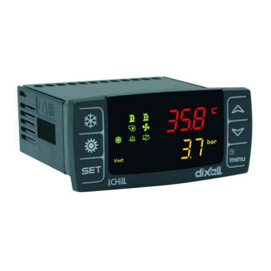
Page 3: User Interface
IC100CX On if heaters are activated (antifreeze heaters or/and boiler) NTERFACE On flashing during defrost delay time. On during defrost On flashing if water flow switch is activated. When the pump is OFF, the led is on flashing to indicate the correct status of the digital input On if at least one water pump is on Display... -
Page 4: Remote Keyboard Vicx610
IC100CX Push and release to visualize all VICX610 the probes configured EMOTE EYBOARD In programming mode it scrolls the parameter list In programming mode increases the value of the parameters. Push and release to visualize all the probes configured In programming mode it scrolls the parameter list In programming mode decreases the value of the parameters... -
Page 5: Display Visualization
IC100CX ILENCING THE UZZER When there is not communication between the keyboard Automatically: just after the alarm condition is recovered. and the instrument the display visualizes ”noL” (no link Manually: push and release one of the keys; the buzzer is message). -
Page 6: Parameters Programming
IC100CX Select “UPL” function with the arrow keys Push SET key again to confirm the new value; after Push “SET” key. The Upload starts immediately. some seconds next parameter will be displayed During this phase the whole regulation is locked and the o o o o Exit the programming mode: push “SET”... -
Page 7: Stand- By Function
IC100CX Push “SET” key when “rSt” is lighted to reset the The icon flashes for 3 seconds when the controller is alarm; after a while the read-out move to next alarm. waiting to turn on/off. To exit the function menu push and release the To move from Chiller mode to Heat Pump mode or vice “menu”... -
Page 8: Keyboard Functions
IC100CX - when two function above are both enabled, 13.9 How to Reset the Alarm Log the lower display shows “Setr” (real set point) Enter the function “menu”. and upper display shows its value. Use o or n keys to find “ALOG” label. Push “SET”... -
Page 9: Installing And Mounting
IC100CX 16. I NSTALLING AND OUNTING 16.1 “C” Format (32*74mm) The instrument shall be mounted on panel, in a 29x71 mm hole, and fixed using the special bracket supplied. 1592022550 Quick reference guide IC100CX GB rel.1.0 03/03/2008 Page 9 di 39... - Page 10 IC100CX 16.2 Remote keyboard Remote terminal “Vertical” shape Mounted on a panel with 72x56 mm cut-out, fixed with screw. To obtain the IP65 protection, even for the panel, use the rubber gasket RGW-V (optional). For wall mounting use the V-KIT plastic adapter as illustrated in figure 2.
-
Page 11: Electrical Wiring
IC100CX 17. E LECTRICAL IRING The controller is provided with removable terminal blocks for wires having section not bigger than 1.0 mm 14 ways for supplay, analogue inputs and digital inputs, 12 ways or 6 ways for relays (depending on model) Note: •... -
Page 12: Alarm Code And Events
IC100CX 18. A LARM ODE AND VENTS Meaning Cause / Origin Instrument behaviour Reset probe Probe Pb1 faulty or disconnected Open collector / alarm Automatic alarm relay ON. if the probe value Buzzer ON. recovers General alarm icon lighted. Alarm code on display. probe Probe Pb2 faulty or disconnected Open collector / alarm... - Page 13 IC100CX If CF01=0,1 and Pb1< AR03 for AR05 Open collector / alarm Automatic: temperature seconds. relay ON. when Pb1 value alarm of the Buzzer ON. increases over supplied General alarm icon AR03+AR04 value. temperature lighted. Alarm code on display. If CF01=0,1 and Pb2< AR03 for AR05 Open collector / alarm Automatic.
- Page 14 IC100CX Evaporator Automatic. If CO11≠0: • If CO11=0 water flow Digital input not active Alarm relay/ open digital input active for AL06; alarm for AL07. the alarm signal is disabled for AL04 starting collector ON. (air/water It turns to manual if from the start-up of the evaporator pump.
- Page 15 IC100CX Compressor 1 Running hour > CO14 Open collector / alarm Manual: maintenance relay ON. Proceed with the hour warning Buzzer ON. reset procedure 13.6 General alarm icon lighted. Alarm code on display. Compressor 2 Running hour > CO15 Open collector / alarm Manual: maintenance relay ON.
- Page 16 IC100CX Condenser Alarm relay/ open Automatic Enabled if AL32≠0. water flow collector ON. Digital input not active If CO26≠0: alarm Buzzer ON. for AL31. digital input active for AL30; General alarm icon It turns to manual if the alarm is disabled for AL04 starting from lighted .
- Page 17 IC100CX ACF2 Configuration Air/air or H2O/air unit and: Open collector / alarm Automatic alarm relay ON After parameter Fa02≠0 and ventilation probe not • Buzzer ON proper debug. configured General alarm icon Chiller parameters configuration • lighted differents from FA13<FA14 and Alarm code on display FA10+FA12+FA13<FA11 Heat Pump parameters configuration...
- Page 18 IC100CX ALOC General alarm Digital input activated for continuous time > Alarm relay/ open Automatic for machine AL21. collector ON. Becomes manual after block Alarm enabled only if AL23=1 Buzzer ON AL20 intervention Flashing flow regulator Manual alarm icon De-activation: digital Code on display input not enabled for continuous time >...
-
Page 19: Connecting Diagram
IC100CX 19. C ONNECTING IAGRAM 19.1 Model with 5 internal relays and 1 modulating output (0..10V or 4..20mA) MF ID1, MF ID2, MF ID5 = multifunction digital inputs ID3 = high pressure digital input ID4 = low pressure digital input RL1 = compressor relay MF RL2, MF RL3, MF RL4, MF RL5 = multifunction relays... - Page 20 IC100CX 19.3 Model with 5 internal relays and pressure trasducer (Pb3) MF ID1, MF ID2, MF ID5 = multifunction digital inputs ID3 = high pressure digital input ID4 = low pressure digital input MF RL2, MF RL3, MF RL4, MF RL5 = multifunction relays Pb1, Pb2, Pb4 = NTC probe or digital input Pb3 = pressure trasducer Tk = output for external fan speed controller...
- Page 21 IC100CX 19.5 Accessories Serie XV: fan speed controller (0,5KW, 1KW and 2,2KW) CW15-KIT e CWC15-KIT: Ichill wiring kit for 5 realys model and 4 relays + 1 triac model XJ485CX: TTL/RS485 serial interface to connect the controller to the supervising system RT314 Kit: relay module (DIN rail mounting) Prog TOOL KIT: programming kit to manage parameters map from the...
-
Page 22: Parameter Table
IC100CX 20. P ARAMETER ABLE SUB MENU SELECTIONS LABEL Meaning Shows the whole set of parameters It contains only the regulation parameters It contains only the configuration parameters It contains only the dynamic Set point parameters It contains only the Energy Saving parameters It contains only the compressor parameters It contains only the fan regulation parameters It contains only the anti freeze parameters... - Page 23 IC100CX ST12 Maximum temperature Set point for outlet water in HP -50.0 °C function (unit without water storage tank) °F ST13 Differential set point for chiller / heat pump function 25.0 °C °F ST14 Offset of the differential for chiller / HP function 25.0 °C °F...
- Page 24 IC100CX CF05 Pb2 configuration 0= Probe not enabled 1= NTC temperature of evaporator outlet 2= Digital Input for antifreeze alarm 3= Digital input for heating demand CF06 Pb3 configuration 0= Probe not enabled 1= NTC temperature condensing control 2= 4..20mA for condensing pressure 3= 4..20ma for Dynamic Set point 4= NTC temperature for anti freeze alarm (water/water) 5= NTC high temperature probe of system inlet water...
- Page 25 IC100CX CF09 ID2 configuration 0= 1 compressor thermal protection 1= Condenser fan thermal protection 2= Evaporator flow switch alarm 3= Remote On/off 4= Cooling/Heating 5= 2 compressor thermal protection 6= 2 compressor or step request (Motocondensing unit) 7= End defrost 8= Energy Saving 9= Anti Freeze alarm 10= 1...
- Page 26 IC100CX CF11 Pb4 configuration in digital input mode 0= 1 compressor thermal protection 1= Condenser fan thermal protection 2= Evaporator flow switch alarm 3= Remote On/off 4= Cooling/Heating 5= 2 compressor thermal protection 6= 2 compressor or step request (Motocondensing unit) 7= End defrost 8= Energy Saving 9= Anti Freeze alarm...
- Page 27 IC100CX CF20 RL4 configuration of the relay 4 0 = Alarm relay 1 = compressor 1 capacity step 2 = compressor 2 3 = ON/OFF ventilation 4 = reversing valve 5 = anti-freezer heaters / integration heater n.1 6 = solenoid valve on water circuit 7 = solenoid valve on water circuit only for heat pump 8= anti-freezer heaters / integration heater n.
- Page 28 IC100CX CF32 Celsius or Fahrenheit selection 0= °C / °BAR 1= °F / °psi CF33 Power supply frequency 0= 50 Hz 1= 60 Hz 2 = DC power supply (PWM configrured as output for an external alarm relay) CF34 Serial Address for monitoring CF35 Remote terminal keyboard 0= Not used...
- Page 29 IC100CX CF41 Open collector output configuration 0 = Alarm relay 1 = compressor 1 capacity step 2 = compressor 2 3 = ON/OFF ventilation 4 = reversing valve 5 = anti-freezer heaters / integration heater n.1 6 = solenoid valve on water circuit 7 = solenoid valve on water circuit only for heat pump 8= anti-freezer heaters / integration heater n.
- Page 30 IC100CX CF46 Controller: visualization in Std-by mode 0 = default visualization (CF36 and CF43 parameters) 1 = the display visualizes “OFF” 2 = the display visualizes “StbY” CF47 Remote keyboard: visualization in Std-by mode 0 = default visualization (CF36 and CF43 parameters) 1 = the display visualizes “OFF”...
- Page 31 IC100CX CO04 OFF delay time between two compressors or Comp. and valve CO05 Output time delay after power supply start-up 10Sec CO06 Compressor On delay time after Pump/”Supply fan” activation CO07 Compressor OFF delay time after Pump/”Supply fan” de- activation CO08 Compressor rotating control 0= Enabled...
- Page 32 IC100CX CO27 Delay between condenser pump shutdown and compressor shutdown CO28 SET hour counter of water condenser pump 10 Hr Compressors in tandem mode CO29 Maximum continuous operating time of a compressor CO30 Compressor start-up delay after activation of the water 10 Sec solenoid valve Modulating evaporator water pump...
- Page 33 IC100CX FA10 Temperature / pressure setpoint for minimum speed in -50.0 °C Decimal summer °F integer Decimal integer FA11 Temperature / pressure setpoint for maximum speed in -50.0 °C Decimal summer °F integer Decimal integer FA12 Proportional band in summer 25.0 °C Decimal...
- Page 34 IC100CX FA25 Hot Start Setpoint -50.0 °C Decimal °F integer FA26 Hot Start differential 25.0 °C Decimal °F integer Password Anti-freeze / Heater parameters Parameter Description Meas. Resolution Ar01 Minimum value of Anti-Freeze Setpoint -50.0 °C Decimal Ar03 °F integer Ar02 Maximum value of Anti-Freeze Setpoint °C...
- Page 35 IC100CX Ar18 “Water pump”/ “Anti-freeze electrical heater” control with unit in OFF or Stand-by 0= Regulation not enabled 1= Regulation enabled 2= Regulation of water pump/anti-freezer on probe PB4 configured as esternal temperature probe 3= Regulation of water pump / anti-freezer heaters on probe PB4 and separate set points Ar19 “Water pump”/ “Anti-freeze electrical heater”...
- Page 36 IC100CX DF01 Defrost control 0= No 1= Yes DF02 Defrost type 0= Temperature / pressure 1= Time 2= External contact DF03 Temperature / pressure Setpoint for starting the defrost -50.0 °C Decimal cycle °F integer Decimal integer DF04 Temperature / pressure Setpoint for stopping the defrost -50.0 °C Decimal...
- Page 37 IC100CX Parameter Description Meas. Resolution AL01 Low pressure alarm delay time AL02 Maximum low pressure alarm events in 1 hour AL03 Low pressure alarm with off compressor 0= Not enabled when compressor Off 1= Enabled when compressor Off AL04 “Water flow/Supply fan thermal protection” alarm delay after “water pump / supply air fan”...
- Page 38 IC100CX AL19 Allows to choose the probe for the anti- freezer heater alarm. 0= Relative to Ar16 parameters in chiller mode - Ar17 in hp. 1= on Pb1 probe 2= on Pb2 probe 3= on Pb3 probe 4= on Pb4 probe AL20 Maximum number of general unit block alarm interventions per hour...
-
Page 39: Technical Data
Output for Hot Key or Persional computer / supervisor systems Remote keyboard Output for remote keyboard Dixell s.r.l. Z.I. Via dell’Industria, 27 32010 Pieve d’Alpago (BL) ITALY tel. +39 - 0437 - 98 33 - fax +39 - 0437 - 98 93 13 E-mail:dixell@dixell.com - http://www.dixell.com...
Need help?
Do you have a question about the iCHiLL 100CX and is the answer not in the manual?
Questions and answers