
Subscribe to Our Youtube Channel
Related Manuals for Gree GWH09AAB-K6DNA1A


Summary of Contents for Gree GWH09AAB-K6DNA1A
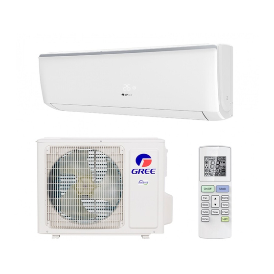
- Page 1 Change for Life Service Manual Models: GWH09AAB-K6DNA1A GWH12AAB-K6DNA1A (Refrigerant R32) GREE ELECTRIC APPLIANCES,INC.OF ZHUHAI...
-
Page 2: Table Of Contents
Service Manual Table of Contents Part Ⅰ : Technical Information ...............1 1. Summary ........................1 2. Specifications ......................2 2.1 Specification Sheet ......................2 2.2 Operation Characteristic Curve ..................4 2.3 Capacity Variation Ratio According to Temperature ............4 2.4 Cooling and Heating Data Sheet in Rated Frequency .............5 2.5 Noise Curve ........................5 3. - Page 3 Service Manual 9. Maintenance ......................33 9.1 Error Code List .......................33 9.2 Procedure of Troubleshooting ..................41 9.3 Maintenance method for normal malfunction ..............56 10. Exploded View and Parts List ..............58 10.1 Indoor Unit ........................58 10.2 Outdoor Unit .........................60 11. Removal Procedure ..................64 11.1 Removal Procedure of Indoor Unit ................64 11.2 Removal Procedure of Outdoor Unit ................69...
-
Page 4: Part Ⅰ : Technical Information
Service Manual Part Ⅰ : Technical Information 1. Summary Indoor Unit: GWH09AAB-K6DNA1A/I GWH12AAB-K6DNA1A/I Outdoor Unit: GWH12AAB-K6DNA3A/O(LC) GWH09AAB-K6DNA3A/O(LC) Remote Controller: YAW1F Technical Information... -
Page 5: Specifications
Service Manual 2. Specifications 2.1 Specification Sheet Model GWH09AAB-K6DNA1A GWH12AAB-K6DNA1A Product Code CB476000900 CB476000301 Rated Voltage 220-240 220-240 Power Rated Frequency Supply Phases Power Supply Mode Outdoor Outdoor Cooling Capacity 2500 3200 Heating Capacity 2800 3400 Cooling Power Input Heating Power Input Cooling Power Current 3.99... - Page 6 Service Manual Model of Outdoor Unit GWH09AAB-K6DNA3A/O GWH12AAB-K6DNA3A/O (LC) Product Code of Outdoor Unit CB478W00200 CB478W00100 ZHUHAI LANDA COMPRESSOR ZHUHAI LANDA COMPRESSOR Compressor Manufacturer/Trademark CO.,LTD CO., LTD Compressor Model QXF-B096zE190A QXF-B096zE190A Compressor Oil FW68DA FW68DA Compressor Type Rotary Rotary L.R.A. Compressor RLA 4.21 4.21...
-
Page 7: Operation Characteristic Curve
Condition Condition Indoor:DB 20°C Indoor:DB 27°C WB19°C Indoor air flow: Super High Indoor air flow: Super High Pipe length:5m Service Manual Pipe length:5m Voltage:230V Voltage:230V 2.2 Operation Characteristic Curve Compressor Speed(rps) Compressor Speed(rps) Cooling Heating 220V Conditions 220V Indoor: DB27°C/WB19°C Outdoor: DB35°C/WB24°C n i l Indoor air flow: High... -
Page 8: Cooling And Heating Data Sheet In Rated Frequency
Service Manual 2.4 Cooling and Heating Data Sheet in Rated Frequency Cooling: Pressure of gas pipe Inlet and outlet pipe Rated cooling Compressor connecting indoor and temperature of heat Fan speed of Fan speed of condition(°C) (DB/WB) Model revolution outdoor unit exchanger indoor unit outdoor unit... -
Page 9: Outline Dimension Diagram
Service Manual 3. Outline Dimension Diagram 3.1 Indoor Unit Φ55 Φ55 Unit:mm Models 09/12K Technical Information... -
Page 10: Outdoor Unit
Service Manual 3.2 Outdoor Unit Unit:mm Unit:mm Technical Information... -
Page 11: Refrigerant System Diagram
Valve Capillary Strainer Service Manual 4. Refrigerant System Diagram COOLING Cooling and heating model Outdoor unit Indoor unit Gas pipe side Valve 4-Way valve Di s charge Heat Suction Accumlator exchanger Compressor (evaporator) Heat exchanger Liquid pipe (condenser) side Valve Strainer Capillary Strainer... -
Page 12: Electrical Part
Service Manual 5. Electrical Part 5.1 Wiring Diagram ●Instruction Symbol Symbol Color Symbol Symbol Color Symbol Name White Green Jumper cap Yellow Brown COMP Compressor Blue Grounding wire YEGN Yellow/Green Black Violet Orange Note: Jumper cap is used to determine fan speed and the swing angle of horizontal lover for this model. ●... - Page 13 Service Manual ● Outdoor Unit 600007000763 600007000687 These wiring diagrams are subject to change without notice; please refer to the one supplied with the unit. Technical Information...
-
Page 14: Pcb Printed Diagram
Service Manual 5.2 PCB Printed Diagram Indoor Unit ● Top view Name Wifi interface Jumper cap Interface of health function live wire Live wire interface Interface of health function neutral wire(only for the model with this function) Neutral wire interface Fan motor interface of PG Fuse Communication interface... - Page 15 Service Manual Outdoor Unit ● Top view Name Compressor wiring terminal Reactor wiring terminal Outdoor fan wiring terminal Terminal of chassis electric heater Terminal of compressor electric heater Terminal of 4-way valve Grounding wire Communication wire Neutral wire Live wire Terminal of electronic expansion valve Terminal of temperature...
-
Page 16: Function And Control
Service Manual 6. Function and Control 6.1 Remote Controller Introduction Buttons on Remote Controller On/Off button Mode button Fan button ▲/ button Swing button Sleep button Temp button Turbo button I Feel button Timer button X-Fan button Light button Icon Display on Remote Controller Temp. - Page 17 Service Manual 1. ON/OFF button Press this button to turn on the unit. Press this button again to turn off the unit. 2. MODE button Each time you press this button,a mode is selected in a sequence that goes from AUTO, COOL, DRY, FAN, and HEAT *, as the following: * Note: Only for models with heating function.
- Page 18 Service Manual TEMP button Press this button, you can see indoor set temperature, indoor ambient temperature on indoor unit’s display. The setting on remote controller is selected circularly as below: no display TURBO button Press this button to activate / deactivate the Turbo function. 9.
- Page 19 Service Manual WIFI Function Press this button to turn on the unit. Press this button again to turn off the unit. Press "MODE" and "TURBO" button simultaneously to turn on or turn off WIFI function. When WIFI function is turned on, the " "...
-
Page 20: Brief Description Of Modes And Functions
Service Manual 6.2 Brief Description of Modes and Functions Indoor Unit ● 1.Basic function of system (1)Cooling mode (1) Under this mode, fan and swing operates at setting status. Temperature setting range is 16~30 (2) During malfunction of outdoor unit or the unit is stopped because of protection, indoor unit keeps original operation status. (2)Drying mode (1) Under this mode, fan operates at low speed and swing operates at setting status. - Page 21 Service Manual (8)I feel control mode After controller received I feel control signal and ambient temperature sent by remote controller, controller will work according to the ambient temperature sent by remote controller. (9)Entry condition for compulsory defrosting function When turn on the unit under heating ode and set temperature is 16 C (or 16.5 C by remote controller), press “+, -, +, -, +, -”...
- Page 22 Service Manual Outdoor Unit ● 1. Cooling mode: Working condition and process of cooling mode: ① When Tindoor ambient temperature≥Tpreset, unit enters into cooling mode. Indoor fan, outdoor fan and compressor start operation. Indoor fan operates according to set fan speed. ②...
- Page 23 Service Manual 7. Auto mode Auto mode is determined by controller of IDU. See IDU logic for details. 8. 8 C heating Set temperature is 8 C. Display board of IDU displays 8 C. Under this mode, “Cold air prevention” function is shielded. If compressor is operating under this mode, fan speed will adjust according to auto fan speed;...
-
Page 24: Part Ⅱ : Installation And Maintenance
Service Manual Part Ⅱ : Installation and Maintenance 7. Notes for Installation and Maintenance Safety Precautions: 10. If the power cord or connection wire is not long enough, please get the specialized power cord or connection wire Important! from the manufacture or distributor. Prohibit prolong the wire by yourself. - Page 25 Service Manual To ensure safety, please be mindful of the following precautions. ●When installing or relocating the unit, be sure to keep the refrigerant circuit free from air or substances other than the specified refrigerant. Any presence of air or other foreign substance in the refrigerant circuit will cause system pressure rise or compressor rupture, resulting in injury.
- Page 26 Service Manual Safety Precautions for Installing and Relocating the Unit: To ensure safety, please be mindful of the following precautions. Warnings 1. When installing or relocating the unit, be sure to keep the refrigerant circuit free from air or substances other than the specified refrigerant.
- Page 27 Service Manual Safety Operation of Flammable Refrigerant Qualification requirement for installation and maintenance man ●All the work men who are engaging in the refrigeration system should bear the valid certification awarded by the authoritative organization and the qualification for dealing with the refrigeration system recognized by this industry. If it needs other technician to maintain and repair the appliance, they should be supervised by the person who bears the qualification for using the flammable refrigerant.
- Page 28 Service Manual Main Tools for Installation and Maintenance 1. Level meter, measuring tape 2. Screw driver 3. Impact drill, drill head, electric drill 4. Electroprobe 5. Universal meter 6. Torque wrench, open-end wrench, inner hexagon spanner 7. Electronic leakage detector 8.
-
Page 29: Installation
Service Manual 8. Installation 8.1 Installation Dimension Diagram Space to the wall At least 15cm At least 15cm Space to the wall Drainage pipe Installation and Maintenance... - Page 30 Service Manual Installation procedures Start installation Preparation before installation Read the requirements select installation Prepare tools for electric connection location Select indoor unit Select outdoor unit installation location installation location Install the support of outdoor unit Install wall-mounting (select it according to the actual situation) frame, drill wall holes Connect pipes of indoor Fix outdoor unit...
-
Page 31: Installation Parts-Checking
Service Manual 8.2 Installation Parts-Checking 8.4 Requirements for electric connection 1. Safety Precaution Name Name (1) Must follow the electric safety regulations when installing Indoor unit Sealing gum the unit. Outdoor unit Wrapping tape (2) According to the local safety regulations, use qualified Support of outdoor power supply circuit and air switch. - Page 32 Service Manual (3) Fix the wall-mounting frame on the wall with tapping screws 5. Connect the Pipe of Indoor Unit (ST4.2X25TA) and then check if the frame is firmly installed by (1) Aim the pipe joint at the corresponding bellmouth.(As show pulling the frame.
- Page 33 Service Manual 7. Connect Wire of Indoor Unit 8. Bind up Pipe (1) Open the panel, remove the screw on the wiring cover and (1) Bind up the connection pipe, power cord and drain hose then take down the cover.(As show in Fig.11) with the band.(As show in Fig.14) (2) Reserve a certain length of drain hose and power cord for installation when binding them.
-
Page 34: Installation Of Outdoor Unit
Service Manual 8.6 Installation of Outdoor unit Refer to the following table for wrench moment of force: Tightening torque(N . m) 1. Fix the Support of Outdoor Unit(Select it according to Hex nut diameter(mm) the actual installation situation) Φ6 15~20 Φ9.52 30~40 (1) Select installation location according to the house structure. -
Page 35: Vacuum Pumping And Leak Detection
Service Manual (3) The water outlet cant be placed in water in order to drain 8.8 Check after Installation and Test smoothly.(As show in Fig.27) operation 1. Check after Installation Check according to the following requirement after finishing installation. The drain hose can't be fluctuant Items to be checked Possible malfunction Has the unit been... -
Page 36: Maintenance
Service Manual 9. Maintenance 9.1 Error Code List Display Method of Outdoor Display Method of Indoor Unit Unit Indicator has 3 kinds of Indicator Display (during display status and during Malfunction blinking, ON 0.5s and OFF Dual-8 A/C status Possible Causes blinking, ON 0.5s and OFF Name 0.5s) - Page 37 Service Manual Display Method of Outdoor Display Method of Indoor Unit Unit Indicator has 3 kinds of Indicator Display (during display status and during Malfunction blinking, ON 0.5s and OFF Dual-8 A/C status Possible Causes blinking, ON 0.5s and OFF Name 0.5s) Code...
- Page 38 Service Manual Display Method of Outdoor Display Method of Indoor Unit Unit Indicator has 3 kinds of Indicator Display (during display status and during Malfunction blinking, ON 0.5s and OFF Dual-8 A/C status Possible Causes blinking, ON 0.5s and OFF Name 0.5s) Code...
- Page 39 Service Manual Display Method of Outdoor Display Method of Indoor Unit Unit Indicator has 3 kinds of Indicator Display (during display status and during Malfunction blinking, ON 0.5s and OFF Dual-8 A/C status Possible Causes blinking, ON 0.5s and OFF Name 0.5s) Code...
- Page 40 Service Manual Display Method of Outdoor Display Method of Indoor Unit Unit Indicator has 3 kinds of Indicator Display (during display status and during Malfunction blinking, ON 0.5s and OFF Dual-8 A/C status Possible Causes blinking, ON 0.5s and OFF Name 0.5s) Code...
- Page 41 Service Manual Display Method of Outdoor Display Method of Indoor Unit Unit Indicator has 3 kinds of Indicator Display (during display status and during Malfunction blinking, ON 0.5s and OFF Dual-8 A/C status Possible Causes blinking, ON 0.5s and OFF Name 0.5s) Code...
- Page 42 Service Manual If malfunction occurs,corresponding code will display and the unit will resume normal until protection or malfunction disappears. Installation and Maintenance...
- Page 43 Service Manual Analysis or processing of some of the malfunction display: 1. Compressor discharge protection Possible causes: shortage of refrigerant; blockage of air filter; poor ventilation or air flow short pass for condenser; the system has noncondensing gas (such as air, water etc.); blockage of capillary assy (including filter); leakage inside four-way valve causes incorrect operation;...
-
Page 44: Procedure Of Troubleshooting
Service Manual 9.2 Procedure of Troubleshooting 1. Malfunction of Temperature Sensor F1, F2 Main detection points: ● Is the wiring terminal between the temperature sensor and the controller loosened or poorly contacted? ● Is there short circuit due to trip-over of the parts? ●... - Page 45 Service Manual 2. Malfunction of Blocked Protection of IDU Fan Motor H6 Main detection points: ● SmoothlyIs the control terminal of PG motor connected tightly? ● SmoothlyIs the feedback interface of PG motor connected tightly? ● The fan motor can't operate? ●...
- Page 46 Service Manual (3) Malfunction of Protection of Jumper Cap C5 Main detection points: ● Is there jumper cap on the mainboard? ● Is the jumper cap inserted correctly and tightly? ● The jumper is broken? ● The motor is broken? ●...
- Page 47 Service Manual 4. Malfunction of Zero-crossing Inspection Circuit Malfunction of the IDU Fan Motor U8 Main detection points: ● Instant energization afte de-energization while the capacitordischarges slowly? ● The zero-cross detectioncircuit of the mainboard is defined abnormal? Malfunction diagnosis process: Start Turn power off for 1minute,the turn...
- Page 48 Service Manual 5. High Temperature and Overload Protection (AP1 below means control board of outdoor unit) E8 Start Normal protection, please use it Unit restarts If the outdoor ambient temperature is after improving the outdoor ambient normally higher than 53°C? temperature Improve the radiating environment of Unit restarts...
- Page 49 Service Manual Outdoor unit: (1) Capacitor charge fault (Fault with outdoor unit) (AP1 below refers to the outdoor control panel) Main Check Points: ●Use AC voltmeter to check if the voltage between terminal L and N on the wiring board is within 210VAC~240VAC. ●Is the reactor (L) correctly connected? Is the connection loose or fallen? Is the reactor (L) damaged? Fault diagnosis process: Turn on the unit...
- Page 50 Service Manual (2) IPM Protection, Out-of-step Fault, Compressor Phase Overcurrent (AP1 below refers to the outdoor control panel) Main check points: ●Is the connection between control panel AP1 and compressor COMP secure? Loose? Is the connection in correct order? ●Is the voltage input of the machine within normal range? (Use AC voltmeter to measure the voltage between terminal L and N on the wiring board XT) ●Is the compressor coil resistance normal? Is the insulation of compressor coil against the copper tube in good condition? ●Is the working load of the machine too high? Is the radiation good?
- Page 51 Service Manual Energize and switch on Use AC voltmeter If the voltage Check the supply to measure the IPM protection between terminal L voltage and voltage between occurs after the and N on wiring machine has run for terminal L and N restore it to board XT is within a period of time?
- Page 52 Service Manual (3) High temperature and overload protection diagnosis (AP1 hereinafter refers to the control board of the outdoor unit) Mainly detect: ●Is outdoor ambient temperature in normal range? ●Are the outdoor and indoor fans operating normally? ●Is the heat dissipation environment inside and outside the unit good? Fault diagnosis process: Overheat and high temperature protection...
- Page 53 Service Manual (4) Start-up failure (following AP1 for outdoor unit control board) Mainly detect: ●Whether the compressor wiring is connected correct? ●Is compressor broken? ●Is time for compressor stopping enough? Fault diagnosis process: Power on the unit Restart it up after Is stop time of the compressor 3 minutes longer than 3 minutes?
- Page 54 Service Manual (5) Out of step diagnosis for the compressor (AP1 hereinafter refers to the control board of the outdoor unit) Mainly detect: ●Is the system pressure too high? ●Is the input voltage too low? Fault diagnosis process: Out of step occurs in Out of step occurs once the operation unit is powered on.
- Page 55 Service Manual (6) Overload and air exhaust malfunction diagnosis (following AP1 for outdoor unit control board) Mainly detect: ●Is the PMV connected well or not? Is PMV damaged? ●Is refrigerant leaked? Fault diagnosis process: 20 minutes after the complete unit is powered off Is the terminal FA for the Connect the...
- Page 56 Service Manual (7) Power factor correct or (PFC) fault (a fault of outdoor unit) (AP1 hereinafter refers to the control board of the outdoor unit) Mainly detect: ●Check if the reactor (L) of the outdoor unit and the PFC capacitor are broken Fault diagnosis process: Start Check wiring of the...
- Page 57 Service Manual (8) Communication malfunction: (following AP1 for outdoor unit control board) Mainly detect: ●Is there any damage for the indoor unit mainboard communication circuit? Is communication circuit damaged? ●Detect the indoor and outdoor units connection wire and indoor and outdoor units inside wiring is connect well or not, if is there any damage? Fault diagnosis process: Start...
- Page 58 Service Manual (9) Malfunction of Overcurrent Protection Main detection points: ● Is the supply voltage unstable with big fluctuation? ● Is the supply voltage too low with overload? ● Hardware trouble? Malfunction diagnosis process: Start Normal fluctuation should be within 10 % Is malfunction Is the supply voltage unstable of the rated voltage on the nameplate...
-
Page 59: Maintenance Method For Normal Malfunction
Service Manual 9.3 Maintenance method for normal malfunction 1. Air Conditioner Cant be Started Up Possible Causes Discriminating Method (Air conditioner Status) Troubleshooting Confirm whether its due to power failure. If yes, No power supply, or poor After energization, operation indicator isnt bright wait for power recovery. - Page 60 Service Manual 4. ODU Fan Motor Cant Operate Possible causes Discriminating method (air conditioner status) Troubleshooting Connect wires according to wiring diagram to Wrong wire connection, or poor Check the wiring status according to circuit make sure all wiring terminals are connected connection diagram firmly...
-
Page 61: Exploded View And Parts List
Service Manual 10. Exploded View and Parts List 10.1 Indoor Unit The component picture is only for reference; please refer to the actual product. Installation and Maintenance... - Page 62 Service Manual Part Code Description GWH09AAB-K6DNA1A/I GWH12AAB-K6DNA1A/I Product Code CB476N00900 CB476N00301 Front Panel 20000300002001T 20000300002001T Display Board 300001000037 300001000037 Front Case 20000200000701 20000200000701 Axile Bush 10542036 10542036 Helicoid Tongue 200006000002 200006000002 Left Axile Bush 10512037 10512037 Rear Case assy 000001000004...
-
Page 63: Outdoor Unit
Service Manual 10.2 Outdoor Unit 21 22 23 24 25 The component picture is only for reference; please refer to the actual product. Installation and Maintenance... - Page 64 Service Manual Part Code Description GWH12AAB-K6DNA3A/O(LC) Product Code CB478W00100 Left Side Plate 01303200P Fan Motor 1501308507 Motor Support 01703136 Condenser Assy 011002000515 Top Cover Sub-Assy 01253081 Rear Grill 01475014 Clapboard Sub-Assy 01233180 Compressor and Fittings 00103925G Compressor Gasket 76710287 4-Way Valve Assy 030152000016 Big Handle 2623343106...
- Page 65 Service Manual The component picture is only for reference; please refer to the actual product. Installation and Maintenance...
- Page 66 Service Manual Part Code Description GWH09AAB-K6DNA3A/O Product Code CB478W00200 Electric Box Assy 100002002426 Electric Box 20113034 Main Board 300027000426 Reactor 43130184 Terminal Board 42010313 Wire Clamp 71010103 Front Grill 22413043 Front Panel 01533034P Axial Flow Fan 10333004 Chassis Sub-assy 017000000134P Fan Motor 1501308507 Small Handle...
-
Page 67: Removal Procedure
Service Manual 11. Removal Procedure Caution: discharge the refrigerant 11.1 Removal Procedure of Indoor Unit completely before removal. Step Procedure 1. Remove filter Panel Open the panel. Loosen the clasp shown in the fig and then pull the left filter and right filer outwards to remove them. - Page 68 Service Manual Step Procedure Panel 3. Remove panel Display Screws Open the front panel; separate the panel rotation shaft from the groove fixing the front panel and then removes the front Front panel panel. Note: The display of some models is fixed on the panel;...
- Page 69 Service Manual Step Procedure Cold plasma generator 6. Remove electric box assy Screws Loosen the connection clasps between Cold plasma generator and electric box, and then remove the cold plasma generator. Electric box Step motor Clasps Grounding Indoor tube screw temperature sensor Electric box assy ①...
- Page 70 Service Manual Step Procedure 7. Remove evaporator assy Remove 3 screws fixing evaporator assy. Screws Connection pipe clamp At the back of the unit, Loosen the clasp,connection pipe clamp and then remove the connection pipe clamp. Clasp Groove Rear Case assy First remove the left side of evaporator from Clasp the groove of bottom shell and then remove...
- Page 71 Service Manual Step Procedure 8. Remove motor and cross flow blade Remove 3 screws fixing motor clamp and then remove the motor clamp. Motor clasp Screws Cross flow Remove the at the connection place of Motor cross flow blade and motor; lift the motor and cross flow blade upwards to remove them.
-
Page 72: Removal Procedure Of Outdoor Unit
Service Manual 11.2 Removal Procedure of Outdoor Unit Steps Procedure 1.Remove big handle Before disassamble. Remove the screws fixing handle、valve big handle cover and then remove them. valve cover 2. Remove top cover top cover Remove the screws fixing top panel and then remove the top panel. - Page 73 Service Manual Step Procedure 3.Remove grille 、protective grille and front panel Remove connection screws between the front grille and the front panel. Then remove the front grille. Remove connection screws connecting the front protective panel with the chassis and the motor support, and grille then remove the front panel.
- Page 74 Service Manual Step Procedure 6.Remove motor and motor support Remove the screws fixing motor and then remove the motor. Remove the screws fixing motor support and then remove the motor support. motor support motor 7.Remove electric box assy Remove the screws fixing electric box assy; cut off electric box assy the tieline;...
- Page 75 Service Manual Step Procedure 9.Remove 4-way valve assy and capillary sub-assy Unsolder the welding joints connecting the 4-way valve assy with capillary sub-assy, compressor and condenser; remove the 4-way valve. 4-way valve assy Note: Before unsoldering the welding joint, wrap the 4-way valve with a wet cloth completely to avoid damage to the valve caused by high temperature.
- Page 76 Service Manual 1.Remove big handle Before disassembly. Remove the connection screw fixing the big handle and then remove the handle. handle 2. Remove top cover top panel Remove connection screws connecting the top cover plate with the front panel and the right side plate, and then remove the top panel.
- Page 77 Service Manual 3.Remove grille axial flow blade and front panel Remove connection screws between the front grille and the front panel. Then remove the front grille. Remove connection screws connecting the front panel with the chassis and the motor support, and then remove the front panel.
- Page 78 Service Manual 6.Remove 4-way valve assy 4-way valve assy Unscrew the fastening nut of the 4-way valve assy coil and remove the coil. Wrap the 4 way Valve Assy with wet cotton and unsolder the 4 weld spots connecting the 4-way valve assy to take it out.(Note: Refrigerant shouldbe discharged firstly.) Welding process should be as quickly as possible and keep wrapping...
- Page 79 Service Manual 9.Remove valves Remove the 2 screws fixing the gas valve and unsolder the welding point between the gas valve and the air-return pipe to remove the gas valve. Remove the 2 screws fixing the liquid valve and unsolder the welding joint connecting the liquid valve to the Y-type pipe to remove the liquid valve.
-
Page 80: Appendix
Service Manual Appendix: Appendix 1: Reference Sheet of Celsius and Fahrenheit Conversion formula for Fahrenheit degree and Celsius degree: Tf=Tcx1.8+32 Set temperature Fahrenheit Fahrenheit Fahrenheit display Fahrenheit display Fahrenheit display Fahrenheit Celsius( Celsius( Celsius( temperature temperature temperature 60.8 69/70 69.8 78/79 78.8 62/63... -
Page 81: Appendix 3: Pipe Expanding Method
Service Manual Appendix 3: Pipe Expanding Method Pipe Note: Pipe cutter Improper pipe expanding is the main cause of refrigerant leakage.Please expand the pipe according to the following steps: Leaning Uneven Burr A:Cut the pip ● Confirm the pipe length according to the distance of indoor unit and outdoor unit. ●... -
Page 82: Appendix 4: List Of Resistance For Temperature Sensor
Service Manual Appendix 4: List of Resistance for Temperature Sensor Resistance Table of Ambient Temperature Sensor for Indoor and Outdoor (15K) Temp( C) Resistance(kΩ) Temp( C) Resistance(kΩ) Temp( Resistance(kΩ) Temp( Resistance(kΩ) 138.1 18.75 3.848 1.071 128.6 17.93 3.711 1.039 121.6 17.14 3.579 1.009... - Page 83 Service Manual Resistance Table of Tube Temperature Sensors for Outdoor and Indoor (20K) Temp( C) Resistance(kΩ) Temp( C) Resistance(kΩ) Temp( Resistance(kΩ) Temp( Resistance(kΩ) 181.4 25.01 5.13 1.427 171.4 23.9 4.948 1.386 162.1 22.85 4.773 1.346 153.3 21.85 4.605 1.307 20.9 4.443 1.269 137.2...
- Page 84 Service Manual Resistance Table of Discharge Temperature Sensor for Outdoor (50K) Temp( C) Resistance(kΩ) Temp( Resistance(kΩ) Temp( C) Resistance(kΩ) Temp( Resistance(kΩ) 853.5 18.34 4.75 799.8 93.42 17.65 4.61 89.07 16.99 4.47 703.8 84.95 16.36 4.33 660.8 81.05 15.75 4.20 620.8 77.35 15.17 4.08...
- Page 85 GREE ELECTRIC APPLIANCES,INC.OF ZHUHAI Add: West Jinji Rd, Qianshan, Zhuhai, Guangdong, China 519070 Tel: (+86-756) 8522218 Fax: (+86-756) 8669426 Email: gree@gree.com.cn Http://www.gree.com HONG KONG GREE ELECTRIC APPLIANCES SALES LIMITED Add: Unit 2612,26/F.,Miramar Tower 132 Nathan Road,TST,Kowloon,HK Tel: (852) 31658898 Fax: (852) 31651029...
Need help?
Do you have a question about the GWH09AAB-K6DNA1A and is the answer not in the manual?
Questions and answers