Table of Contents
Advertisement
Quick Links
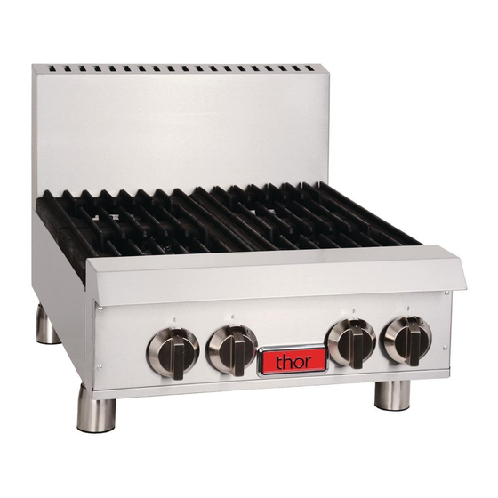
Thor Gas Hot Plate
Technical Service Manual
Model: GH107-P , GH107-N
IMPORTANT FOR FUTURE REFERENCE
Please complete this information and retain this manual for the life of the equipment. For Warranty
Service and/or parts, this information is required.
Model Number
WARNING: For your safety, do not store or use gasoline or other flammable vapors or
liquids in the vicinity of this or any other appliances. Keep the area free and clear of
combustible.
WARNING:Improper installation, adjustment, alteration, service or maintenance can
cause property damage, injury, or death. Read the installation operating and
maintenance instructions thoroughly before installing, or servicing this equipment.
WARNING:Instructions must be posted in a prominent location. All safety
precautions must be taken in the event the user smells gas. Safety information can be
obtained from your local gas supplier.
Serial Number
15 Badgally Road, Campbelltown
NSW 2560
Date Purchased
Advertisement
Table of Contents

Subscribe to Our Youtube Channel
Related Manuals for THOR GH107-P


Summary of Contents for THOR GH107-P
- Page 1 Thor Gas Hot Plate Technical Service Manual Model: GH107-P , GH107-N IMPORTANT FOR FUTURE REFERENCE Please complete this information and retain this manual for the life of the equipment. For Warranty Service and/or parts, this information is required. Model Number...
-
Page 2: Table Of Contents
Table of Contents Introduction Specification Dimensions Installation 4 ~ 6 Operation 7 ~ 9 Cleaning and Maintenance 10 ~ 12 Troubleshooting 13 ~ 23 Conversion from NG to LPG and vice-versa Explosion Drawing (ALL PARTS) Parts List 25 ~ 26 Explosion Drawing (SPARE PARTS) Spare Parts List... -
Page 3: Introduction
Introduction We are confident that you will be delighted with your Thor Gas Hot Plate, and it will become a most valued appliance for you. To ensure you receive the utmost benefit from your new Gas Hot Plate, there are two important things you need to Firstly: Please read the instruction book carefully and follow the directions given. -
Page 4: Specification
Commercial heavy duty hot plate with cast iron trivets and burners, and fitted with full pilot and flame failure protection. Pack Contents The following is included: Thor Gas Hot Plate Feet Instruction Manual Gas Supply Requirements Natural Gas... -
Page 5: Dimensions
Dimensions GH107-P / GH107-N... -
Page 6: Installation 4
Installation Installation Requirements NOTE: • It is most important that this appliance is installed correctly and that operation is correct before use. Installation shall comply with local gas, health and safety requirements. • This appliance shall be installed with sufficient ventilation to prevent the occurrence of unacceptable concentrations of substances harmful to health. - Page 7 Installation Clearances NOTE: Only non-combustible materials can be used in close proximity to this appliance. Combustible Surface Non Combustible Surface Left / Right Hand Side 250mm Rear 250mm Assembly NOTE: • This appliance is assembled before delivery except feet. • This appliance is fitted with adjustable feet to enable the appliance to be positioned securely and level. This should be carried out on completion of the gas connection.
- Page 8 Installation 6. Check that the gas operating pressure. NOTE: The operating pressure to be measured at the manifold test point and with 2 burners operating at the ‘High Flame’ setting. 7. Turn off the mains gas supply and bleed the gas out of the appliance gas lines. 8.
-
Page 9: Operation 7
Operation Operation Guide CAUTION: • This appliance is for professional use and is only to be used by qualified persons. • Only authorized service persons are to carry out installation, servicing or gas conversion operation operations. • Components having adjustments protected by the manufacturer should not be adjusted by the user/operator. 1. - Page 10 Operation 1. Lighting the Main Burners The hot plates are fitted with individual standing pilots for each open burner which allows the main burners to be turned ON- OFF without the need to manually re-light the burner each time that it is turned ON, as the burner will be automatically lit itself by the pilot burner.
- Page 11 Operation Main burner air supply: 1. For efficient burner operation, a proper balance of gas volume and primary air supply must be maintained which will result in complete combustion. Insufficient air supply results in a yellow streaming flame. Primary air supply is controlled by an air shutter on the front of the burner. 2.
-
Page 12: Cleaning And Maintenance
Cleaning and Maintenance CAUTION: Always turn off the gas supply before cleaning. This appliance is not water proof. Do not use water jet spray to clean this appliance. GENERAL Clean the Gas Hot Plate regularly. A clean Gas Hot Plate looks better, will last longer and will perform better. - Page 13 Cleaning and Maintenance Pic1 Trivets and Burners a. Remove the trivets from the top of the appliance (Refer to Pic1). b. Remove the burner from the top of the bracket of appliance (Refer to Pic2). c. The trivets and burners should be cleaned with a mild detergent and hot water solution using a soft bristled brush.
- Page 14 Cleaning and Maintenance NOTE: All maintenance operations should only be carried out by a qualified service person. To achieve the best results, cleaning must be regular, thorough and all controls and mechanical parts should be checked and adjusted periodically by a qualified service person. If any small faults occur, have them attended to promptly.
-
Page 15: Troubleshooting 13
Trouble Shooting This section provides an easy reference guide to the more common problems that may occur during the operation of your equipment. The fault finding guide in this section is intended to help you correct, or at least accurately diagnose problems with your equipment. Although this section covers the most common problems reported, you may encounter a problem not covered in this section. - Page 16 Trouble Shooting BURNER PROBLEMS LIFTING BURNER FLAMES: Excessive primary air can cause flames to lift and blow off the burner ports which can be noisy as well as inefficient. More importantly however is the production of dangerous carbon monoxide under this condition.
- Page 17 Trouble Shooting BURNER PROBLEMS– cont’d. FLOATING FLAMES: The difference between floating flames and lifting (or blowing) flames should be clearly understood. Both conditions are undesirable, but the causes and corrective steps are different. Floating flames are lazy looking. They do not have well defined cones, and appear to be “reaching” for the air. They are long, ill- defined, quite flames which roll around in the combustion chamber sometimes completely off the ports.
- Page 18 Trouble Shooting PILOT TROUBLE SHOOTING Fault Possible Cause Remedy No gas supply or gas isolation valve Ensure gas isolation valve is turned on, Pilot won’t light. is OFF. and that gas tanks are not empty. Pilot burner is clogged/blocked. Check the pilot burner if clogged, and clean if necessary.
- Page 19 Trouble Shooting PILOT TROUBLE SHOOTING – cont’d.: CHECKING & CLEANING OF THE PILOT INJECTOR: 1. Visually check the orifice of the pilot THERMOCOUPLE injector if clogged, damaged or blocked. PILOT BURNER If it cannot be checked visually, try to blow air in the injector and check if there is air coming out of the orifice.
- Page 20 Trouble Shooting PILOT TROUBLE SHOOTING – cont’d.: PILOT BURNER REMOVAL: 1. Turn-off the pilot. 2. Shut-off the main isolation valve and follow the lock-out /tag-out procedure. 3. Loosen the screw which locks the pilot burner in place. See pilot burner assembly photo. 4.
- Page 21 Trouble Shooting MAIN BURNER TROUBLE SHOOTING: Fault Possible Cause Remedy No gas supply or gas isolation Ensure gas isolation valve is turned Main burner will not light. valve is OFF. on, and that gas tanks are not empty. Insufficient gas supply pressure. Adjust the gas supply pressure to required standard.
- Page 22 Trouble Shooting MAIN BURNER TROUBLE SHOOTING – cont’d.: SAFETY GAS VALVE REMOVAL: 1. Turn-off the pilot. 2. Shut-off the main isolation valve and follow the lock- out/tag-out procedure. 3. Remove the drip tray. 4. Remove the knob and control panel cover. 5.
- Page 23 Trouble Shooting MAIN BURNER TROUBLE SHOOTING – cont’d.: GAS MANIFOLD ASSEMBLY REMOVAL: 1. Turn-off the pilot. 2. Shut-off the main isolation valve and follow the lock- out/tag-out procedure. 3. Disconnect the manifold from the gas regulator. 4. Remove the drip tray. 5.
- Page 24 Trouble Shooting MAIN BURNER TROUBLE SHOOTING – cont’d.: MAIN BURNER LOW FLAME ADJUSTMENT: ADJUSTMENT 1. Light the main burner that you want to be adjusted. KNOB 2. Set the dial/knob to low flame. 3. Pull-out and remove the knob of the safety gas valve. 4.
- Page 25 Trouble Shooting CONVERTING FROM LPG TO NG AND VICE-VERSA: CONVERTER 1. Turn-off the pilot. COVER 2. Shut-off the main isolation valve and follow the lock-out/tag-out procedure. 3. Remove the gas regulator. 4. Remove the converter cover from the regulator. Use a 22mm spanner. 5.
- Page 26 Trouble Shooting IMPORTANT: Only genuine authorized replacement parts should be used for the servicing and repair of this appliance. The instructions supplied with the parts should be followed when replacing components. For further information and servicing instructions, contact the manufacturer’s technical service team. When ordering replacement parts, please write down the part number and the description listed below.
-
Page 27: Explosion Drawing (All Parts)
Explosion Drawing (ALL PARTS) GH107-P / GH107-N... -
Page 28: Parts List 25
PARTS LIST DESCRIPTION MODEL CODE Dial GH107-P / GH107-N 01.09.1050334 Ornament GH107-P / GH107-N 01.05.1028910 Thor LOGO GH107-P / GH107-N 04.07.1340203 Control panel GH107-P / GH107-N 01.09.1050398 Safety Valve(A60U) GH107-P / GH107-N 01.20.1068524 (accessories) Control rack GH107-P / GH107-N 01.05.1028909 Manifold assy. - Page 29 PARTS LIST – cont’d. DESCRIPTION MODEL CODE Flame Device system –FRONT GH107-P / GH107-N 01.22.1069539 (Injector not included) ODS injector-0.20 GH107-P 01.20.1068546 ODS injector-0.40 GH107-N 01.20.1068547 Main pipe assy.-rear GH107-P / GH107-N 01.24.1070901 Frame weld assy. GH107-P / GH107-N 06.05.1471835...
-
Page 30: Explosion Drawing (Spare Parts)
Explosion Drawing (Spare parts) GH107-P / GH107-N... -
Page 31: Spare Parts List
Spare Parts List DESCRIPTION MODEL CODE Dial GH107-P / GH107-N 01.09.1050334 Thor LOGO GH107-P / GH107-N 04.07.1340203 Safety Valve(A60U) GH107-P / GH107-N 01.20.1068524 (accessories) Manifold Assembly GH107-P / GH107-N 01.24.1070877 (Include A60U valve) Main Pipe Assembly - GH107-P / GH107-N 01.24.1070902...
Need help?
Do you have a question about the GH107-P and is the answer not in the manual?
Questions and answers