Advertisement
Available languages
Available languages
Quick Links
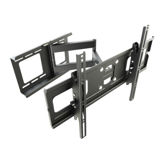
Wandhalterung für TV / Monitor
2
x
ACHTUNG: NIEMALS DAS MAXIMAL
ZULÄSSIGE BELASTUNGSGEWICHT
!
ÜBERSCHREITEN. MISSACHTUNG
KANN ZU SACHSCHÄDEN ODER
SCHWEREN VERLETZUNGEN FÜHREN!
Bitte überprüfen Sie VOR der Montage den Lochabstand zwischen den VESA Befestigungslöchern
!
Diese Wandhalterung unterstützt folgende Lochabstände:
Horizontal / Wageerecht
Vertikal / Senkrecht
RW R05
RW R15
an Ihrem Bildschirm
Horizontal / Waagerecht
100x100
400x100
500x400
100x200
400x200
500x500
200x100
400x300
600x100
200x200
400x400
600x200
300x100
500x100
600x300
300x200
500x200
600x400
300x300
500x300
VESA - Befestigungslöcher
Vertical /
Senkrecht
min. 70mm - max. 600mm
min. 70mm - max. 400mm
VESA 400x400
(121lbs)
MONTAGEANLEITUNG
Bildschirm Rückseite
VESA 600x400
55kg
95kg
(209lbs)
MAX
MAX
English
Deutsch
v.17.03
Advertisement

Related Manuals for ricoo RW R15


Summary of Contents for ricoo RW R15
- Page 1 Vertikal / Senkrecht min. 70mm - max. 400mm 100x100 400x100 500x400 VESA 400x400 VESA 600x400 RW R05 100x200 400x200 500x500 55kg 95kg 200x100 400x300 600x100 200x200 400x400 600x200 RW R15 (121lbs) (209lbs) 300x100 500x100 600x300 300x200 500x200 600x400 300x300 500x300 English Deutsch...
- Page 2 ACHTUNG: Lesen Sie die gesamte Bedienungsanleitung durch, bevor Sie mit der Montage beginnen. WARNUNG • Beginnen Sie nicht mit der Montage, bis Sie alle Anweisungen und Warnungen, welche in dieser Montageanleitung vorhanden sind, durchgelesen und verstanden haben. Wenn Sie Fragen zu den Anweisungen oder Warnungen haben, kontaktieren Sie bitte Ihren Händler.
- Page 3 Lieferumfang WICHTIG: Stellen Sie vor der Montage sicher, dass alle Teile welche hier aufgeführt sind, bei der Lieferung dabei sind. Sollten Teile fehlen oder defekt sein, kontaktieren Sie Ihren Händler. Wandhalterung, vormontiert (x1) Schiene, vormontiert (x2) Plastikbeutel Beachten Sie: Die Durchnummerierung auf dem Plastikbeutel kann abweichen / komplett fehlen! oder S10 (x6) M8 (x6)
- Page 4 Schritt 1 Wandplatte Für Erleichterung der Montage wird eine Wasserwaage mitgeliefert. Wir empfehlen jedoch den Einsatz einer professionelen Wasserwaage. Schritt 2 Var.1: Befestigung an der Massivbetonwand Achtung: Mitgelieferte Dübel sind nur für Massivbetonwände geeignet! Montagelöcher markieren. Montagelöcher bohren. Wandplatte an die Wand anschrauben.
- Page 5 Var.1: Befestigung an der Holzbalkenwand Holzbalken mit Balkenfinder finden und die Montagelöcher markieren. Montagelöcher markieren. Balkenfinder Montagelöcher bohren. Holzbalken Wandplatte an die Wand anschrauben. • Stellen Sie sicher, dass die Befestigungsschrauben in der Mitte der Balken verankert sind. Die Verwendung eines Balkenfinders wird dringend empfohlen.
- Page 6 Schritt 3 3b. Befestigung an der Massivbetonwand Lockern Sie die gezeigten Schrauben in der Mitte der Frontplatte und richten Sie die Frontplatte so aus, dass diese parallel zur Wandplatte ist. Ziehen Sie nach der Ausrichtung alle 4 Schrauben wieder mittelfest an. °...
- Page 7 Schritt 5 Var.1: Für Bildschirme mit gewölbter Rückseite Bildschirm Rückseite G I K M x4 * * Benutzen Sie die für Ihren Bildschirm passende Schrauben und Abstandshalter. Var.2: Für Bildschirme mit flacher Rückseite H J L N x4 * Bildschirm Rückseite G I K M x4 */** * Benutzen Sie die für Ihren Bildschirm passende Schrauben und Abstandshalter.
- Page 8 Schritt 6 Bildschirm Neigunsverstellmutter 180° 180° 180° ° ± Fixierung Schritt 7 (optional) Diese Wandhalterung besitzt eine Drehfunktion der Frontplatte. Somit ist der Bildschirm in Horizontaler / Waagerechten um +/-6° drehbar. Dies hat den Vorteil, dass Sie den Bildschirm jederzeit horizontal ausrichten können. Um dies zu ermöglichen sind die vier Einstellschrauben an der Frontplatte vom Werk aus so eingestellt, dass Sie den Bildschirm jederzeit mit den Händen ohne die Schrauben lockern zu müssen und ohne großen Kraftaufwand waagerecht gerade stellen können, was das Ausrichten ohne Extra-Werkzeug ermöglicht.
- Page 9 70mm - max. 400mm Vertical / Perpendicularly 100x100 400x100 500x400 VESA 400x400 VESA 600x400 RW R05 100x200 400x200 500x500 55kg 95kg 200x100 400x300 600x100 200x200 400x400 600x200 RW R15 (121lbs) (209lbs) 300x100 500x100 600x300 300x200 500x200 600x400 300x300 500x300 Deutsch English...
- Page 10 NOTE: Read the entire instruction manual before you start installation and assembly. WARNING • Do not begin the installation until you have read and understood all the instructions and warn- ings contained in this installation sheet. If you have any questions regarding any of the instruc- tions or warnings, please contact your local distributor.
-
Page 11: Component Checklist
Component checklist IMPORTANT: Ensure that you have received all parts according to the component checklist prior to installation. If any parts are missing or faulty, telephone your loacal destributor for a replacement. Wall mount, pre-assembled (x1) Rail, pre-assembled (x2) Plastic bag Please note: The numbering on the plastic bag may differ / completely missing! S10 (x6) M8 (x6) - Page 12 Step 1 Wall plate For convenience of mounting a spirit level is included. We recommend using a professional level. Step 2 Var.1: Solid concrete mounting Warning: Supplied plastic anchors are only suitable for solid concrete walls! Find and mark the exact location of mounting holes.
- Page 13 Var.1: Wood stud mounting Find the wood stud with studfinder Mark the exact location of mounting holes. Stud finder Drill pilot holes Wood stud Screw the wall mount onto the wall. • Make sure that mounting screws are anchored into the center of the studs. The use of a stud finder is highly recommended. •...
- Page 14 Step 3 3b. Befestigung an der Massivbetonwand Loosen the shown screws in the middle of front panel and align the front plate making sure that it is parallel to the wall plate. After the alignment tighten all 4 screws at medium strength. °...
- Page 15 Step 5 Var.1: For display with a curved back Display back G I K M x4 * * Use the matching screws and spacers for your display. Var.2: For display with a flat back H J L N x4 * Display back G I K M x4 */**...
- Page 16 Step 6 Display Tilt adjustment nut 180° 180° 180° ° ± Fixation Step 7 (optional) This Wall Bracket has a rotation function of the front panel. Therefore the screen is turnable +/-6° horizontally / vertically. This has the advantage that you can align horizontally the screen at any time. To permit this function, the four adjusting screws on the front panel are set in the factory so that you can adjust the screen straightly with your hands without loosen the screws which is possible without extra tools.
Need help?
Do you have a question about the RW R15 and is the answer not in the manual?
Questions and answers