Table of Contents
Advertisement
Quick Links
Advertisement
Table of Contents

Subscribe to Our Youtube Channel
Related Manuals for Meatest M641


Summary of Contents for Meatest M641
- Page 1 M641 Programmable RTD Simulator Operation manual...
-
Page 3: Table Of Contents
M641 Programmable RTD Simulator MEATEST Content BASIC INFORMATION........................5 PREPARATION FOR USE ........................5 2.1........5 NSPECTING PACKAGE CONTENTS SELECTING THE INSTALLATION LOCATION 2.2............................5 OWER ON 2.3..........................6 UP TIME 2.4........................6 AFETY PRECAUTIONS DESCRIPTION ............................. 7 3.1. - Page 4 Table 5 Keyboard codes ....................... 60 Table 6 SCPI error codes...................... 63 Table 7 M641 Resistance accuracy..................68 Table 8 M641 Pt simulation accuracy ................... 68 Table 9 M641 Ni simulation accuracy .................. 68 Table 10 M641 Typical frequency response ................. 68...
-
Page 5: Basic Information
Low thermal voltage relays and stable resistors are used as main parts of the RTD Simulator. Actual set values are displayed on high resolution TFT display. M641 is sophisticated instrument with its own re-calibration procedure. The procedure enables to correct any deviation in resistance without any mechanical adjustment. -
Page 6: Warm-Up Time
MEATEST M641 Programmable RTD Simulator Figure 1 Starting Screen The instrument performs internal hardware checks for app. 5 seconds. After the tests conclude, the instrument is set to “Startup” preset. This preset is adjustable however, the instrument will always start with OPEN terminals. -
Page 7: Description
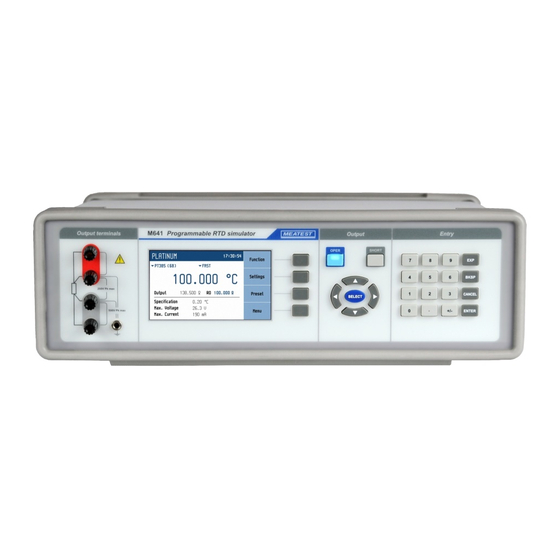
M641 Programmable RTD Simulator MEATEST 3. Description 3.1. Front panel Figure 2 Front panel On the front panel there are located all main control keys, display and output terminals. Output terminals Four wire output terminals. Measuring (evaluation) circuit can be connected by 2, 3 or 4 wires. Both sides (red and grey) are floating up to 500Vpk against the case (PE). - Page 8 MEATEST M641 Programmable RTD Simulator The display is divided into four sections: A. Information line Selected function (RESISTANCE, PLATINUM, …) Time B. Main area This section displays the set-up values of generated signals and the data related to the simulator status.
-
Page 9: Rear Panel
M641 Programmable RTD Simulator MEATEST OPER (Operate key) OPER key connects / disconnects selected value to the output terminals. Connected output terminals are indicated by the lit LED in the key. SHORT (Short key) Active SHORT key (LED in the key is ON) replaces the main value with the short circuit. Also the short circuit must be connected to the output terminals by the OPER key. -
Page 10: Operation
MEATEST M641 Programmable RTD Simulator 4. Operation 4.1. Connection and disconnection of output terminals Set value is connected (disconnected) to the output terminals after pressing OPER key. Connected output terminals are indicated by the lit LED in the key. Disconnected output terminals can be used for “Open terminals” simulation. “Short circuit” is simulated after pressing SHORT key. -
Page 11: Figure 6 Platinum Screen
M641 Programmable RTD Simulator MEATEST Platinum Offers direct setting of temperature of simulated platinum thermometer. Figure 6 Platinum screen Editable parameters: Temperature: -200 °C … +850 °C (-328 F … 1562 F) R0 value: 100 Ω … 1 kΩ Temperature standard:... -
Page 12: Figure 8 User Function Screen
MEATEST M641 Programmable RTD Simulator User function Offers simulation of conversion curve defined by a table. User can define more conversion curves. Values between defined points are linearly interpolated. Figure 8 User function screen Editable parameters: Main value: according to the function... -
Page 13: Figure 10 New User Function
M641 Programmable RTD Simulator MEATEST Creating a new table Pressing the Edit softkey upon plain curve opens this submenu: Figure 10 New user function Curve name – table name is set using ▲,▼ (character selection) and ◄, ► (position) cursor keys. -
Page 14: Figure 12 User Function Edit
MEATEST M641 Programmable RTD Simulator Editing an existing table Existing table can be edited in the same way as it can be created. Editable entries (Curve name, Unit, Lookup table points) are selected using the key. SELECT Figure 12 User function edit Timing Offers simulation of time-varying resistance defined by a table. -
Page 15: Figure 14 Time Sequence List
M641 Programmable RTD Simulator MEATEST Figure 14 Time sequence list Menu shows a list of all sequences. Softkeys on the right hand side of the panel have these functions: Edit – edit selected sequence. Sequence can be selected using cursor keys where ◄, ► skip through pages. -
Page 16: Figure 16 Timing Sequence Point Editing
MEATEST M641 Programmable RTD Simulator Timing table – a list of values in Ω and their durations in seconds. Browsing through the table is done by ▲,▼ cursor keys. Editing is done using these softkeys: Add – create a new point. -
Page 17: Setting The Value Of Output Signal
M641 Programmable RTD Simulator MEATEST 4.4. Setting the value of output signal Edit mode Parameters of output signal can be changed in Edit mode. Only parameters displayed in blue color can be changed. Display can be switched to edit mode in different ways:... -
Page 18: Parameter Settings (Settings Menu)
MEATEST M641 Programmable RTD Simulator 4.5. Parameter settings (settings menu) Settings menu is displayed after pressing „Settings“ softkey in main function window. It won’t appear in editing mode so when in editing mode you have to press “Cancel” first. Figure 19 Settings menu In settings menu you can edit all available auxiliary parameters of the current function. -
Page 19: Main Menu
M641 Programmable RTD Simulator MEATEST 4.7. Main menu Main menu is displayed after pressing „Menu“ softkey. In main menu you can set all the parameters available. Figure 21 Main menu Required menu item is highlighted using cursor keys ▲,▼ or display softkeys. Highlighted menu is selected by pressing key or „Select“... - Page 20 MEATEST M641 Programmable RTD Simulator SHORT value is lower than min (R1, R2). Platinum standard Platinum thermometers can be simulated according to the different standards. Available standards are: PT385 (68) DIN, standard EN60751, temperature scale IPTS68 (A=3.90802e-3, B=-5.80195e-7, C=-4.2735e-12) PT385 (90) DIN, standard EN60751, temperature scale ITS90 (A=3.9083e-3, B=-5.775e-7, C=-4.18301e-12)
-
Page 21: Calibration Mode
M641 Programmable RTD Simulator MEATEST Active bus Active bus setting. Only active bus can be used for remote control. RS232 Baudrate RS232 communication baudrate setting. The same baudrate must be used in the controller. GPIB Address GPIB address setting. Each instrument connected to the GPIB bus must have a unique address. -
Page 22: Table 1 M641 Calibration Points
80 1 M 200 2 M 400 3,99 M 1 k 7,8 M 5 k 15 M 50 k 30 M 200 k 60 M 500 k 120 M 1 M Table 1 M641 Calibration points Operation manual... -
Page 23: Figure 23 Calibration Point Screen
wire connection mode. Figure 23 Calibration point screen Using cursor keys ▲,▼, ◄, ► adjust resistance value in M641 according to the ohm meter. Confirm new calibration value by pressing “Save” softkey. Repeat above described procedure for all resistance elements. -
Page 24: Performance Verification Test
MEATEST M641 Programmable RTD Simulator 5. Performance verification test Parameter verification procedure is described in the chapter. Verification procedure is based on measuring resistance on the simulator output terminals with standard multimeter in recommended points. Required equippment Ohm-meter nominal accuracy 0.001% in range 1 to 1.2 M (type Fluke 8508A or similar) RTD simulator setting Switch RTD simulator to the resistance function. -
Page 25: Remote Control
M641 Programmable RTD Simulator MEATEST 6. Remote control RTD simulator can be controled via RS232, GPIB, LAN and USB interface. The simulator can be only controlled by one of interfaces at a time. It is therefore necessary to select ans set-up one of the interfaces using the system menu. -
Page 26: Gpib Interface (Option)
GPIB Interface (option) The simulator can be controlled via GPIB (General Purpose Interface Bus) interface. Following equipment is required: M641 simulator with LAN, USB, IEEE488 bus option Personal Computer (or other controlling device) with GPIB interface GPIB cable The GPIB interface must be selected from simulator system menu to be in operation (SETUP- >Interface->Active bus). -
Page 27: Lan Interface (Option)
LAN Interface allows communication with simulator using Telnet protocol. A proper setting must be established. Following equipment is required: M641 simulator with LAN, USB, IEEE488 bus option Personal Computer (or other controlling device) with LAN interface LAN cable ... -
Page 28: Usb Interface (Option)
USB Interface (option) The simulator can be controlled via USB (Universal Serial Bus) interface. Following equipment is required: M641 simulator with LAN, USB, IEEE488 bus option Personal Computer (or other controlling device) with USB interface (USB type A connector) Standard USB A-B cable ... -
Page 29: Command Syntax
M641 Programmable RTD Simulator MEATEST 6.5. Command syntax The commands described in this chapter can be issued through all buses (RS232/GPIB/LAN/USB). All commands listed in this chapter are explained in two columns: KEYWORD and PARAMETERS. KEYWORD column includes the name of the command. Each command includes one or more keywords. -
Page 30: Scpi Command Tree
MEATEST M641 Programmable RTD Simulator 6.6. SCPI Command Tree This chapter summarizes all public SCPI commands supported by device in alphabetic order. Detailed description follows in next chapter. :CALibration :RESistance :AMPLitude(?) <DNPD> :SELect(?) <DNPD> :SECure :PASSword(?) <DNPD> :EXIT :DISPlay :ANNotation... - Page 31 M641 Programmable RTD Simulator MEATEST :RCOunt? <DNPD> :ROW<IND_ROW> :AMPLitude(?) <SPD> :RDELete :SAVE :UNIT(?) <SPD> :STATus :OPERation :CONDition(?) <DNPD> :ENABle(?) <DNPD> [:EVENt]? <DNPD> :NTRansition(?) <DNPD> :PTRansition(?) <DNPD> :QUEStionable :CONDition(?) <DNPD> :ENABle(?) <DNPD> [:EVENt]? <DNPD> :NTRansition(?) <DNPD> :PTRansition(?) <DNPD> :SYSTem :BEEPer :STATe(?) {ON|OFF|1|0} :VOLume(?) <DNPD>...
-
Page 32: Standard Status Data Structures
MEATEST M641 Programmable RTD Simulator *STB? *TST? *WAI 6.7. Standard Status Data Structures RTD simulator meets standard protocol according to the standard IEEE488.2. The protocol can be used for checking of error and status behavior of the device. It enables single-wire transmitting of SRQ command. - Page 33 M641 Programmable RTD Simulator MEATEST Status data structure contains following registers: STB – Status Byte Register SRE – Service Request Enable Register ESR – Event Status Register ESE – Event Status Enable Register Output Queue STB Status Byte Register STB is main register where information from other status registers and from output queue is collected.
-
Page 34: Scpi Standard Commands
MEATEST M641 Programmable RTD Simulator Operation Complete, bit 0. This event bit is generated in response to the *OPC command. It indicates that the device has completed all selected pending operations. ESE Event Status Enable Register The Event Status Enable Register allows one or more events in the Event Status Register to be reflected in the ESB summary-message bit. - Page 35 M641 Programmable RTD Simulator MEATEST *IDN? Syntax: *IDN? Description: This command returns the identification of the manufacturer, model, serial number and firmware revision. Parameters: <CPD> manufacturer <CPD> model <DNPD> serial number <DNPD> frimware version Remarks: Overlapped command Example: *IDN? Response: MEATEST,M641,620151,1.00...
- Page 36 MEATEST M641 Programmable RTD Simulator *WAI Syntax: *WAI Description: Prevents the instrument from executing any further commands or queries until all previous remote commands have been executed. Parameters: None Remarks: Sequential command Example: *WAI *RST Syntax: *RST Description: This command resets the device to its initial factory-set state. This state may be different from the “Startup”...
- Page 37 M641 Programmable RTD Simulator MEATEST *SRE Syntax: *SRE *SRE? Description: This command allows set condition of the Service Request Enable register. Since bit 6 is not used, the maximum value is 191. Parameters: <DNPD> Service Request Enable register Remarks: Overlapped command...
-
Page 38: Scpi Commands
MEATEST M641 Programmable RTD Simulator 6.9. SCPI Commands This chapters describes all public SCPI commands in detailed form. The commands here are in alphabetic order. :CALibration:RESistance:AMPLitude Syntax: :CALibration:RESistance:AMPLitude <DNPD> :CALibration:RESistance:AMPLitude? Description: This command sets calibration value of particular internal resistance standard at output terminals including all parasitic resistances inside simulator. - Page 39 M641 Programmable RTD Simulator MEATEST :CALibration:SECure:PASSword Syntax: :CALibration:SECure:PASSword <DNPD> Description: This command validates entered password and enables calibration access if verification is successful. Access is invalidated after reset or if CAL:SEC:EXIT command is issued. Calibration password can be changed from simulator system menu SETUP->Calibration- >Change password.
- Page 40 MEATEST M641 Programmable RTD Simulator :DISPlay:ANNotation:CLOCk[:STATe] Syntax: :DISPlay:ANNotation:CLOCk[:STATe] <BOOL> :DISPlay:ANNotation:CLOCk[:STATe]? Description: This command enables/disables showing actual time in title on device screen Parameters: <BOOL> {ON|OFF|1|0} (default 1) ·ON actual time is shown ·OFF actual time is hidden ·1 same as ON ·0...
-
Page 41: Table 4 Output Command Structure
M641 Programmable RTD Simulator MEATEST :OUTPut:SHORt <BOOL> :OUTPut:SHORt? Description: This command turns on short function. “Short” is activated only if output terminals are switched on (see OUTP:STAT command). Parameters: <BOOL> {ON|OFF|1|0} (default 0) ·ON short is set if output is on ·OFF... - Page 42 MEATEST M641 Programmable RTD Simulator :OUTPut:SWITching Syntax: :OUTPut:SWITching <CPD> :OUTPut:SWITching? Description: If output amplitude is changed and output terminals are already switched on, some glitches appear at output terminals. This setting allows selecting a method how new resistance at output terminals is achieved.
- Page 43 M641 Programmable RTD Simulator MEATEST [:SOURce]:NICKel:ZRESistance Syntax: [:SOURce]:NICKel:ZRESistance <DNPD>[<UNIT>] [:SOURce]:NICKel:ZRESistance? Description: This command sets resistance at 0 °C for Nickel function. Parameters: <DNPD> Range 100.0 ... 1000.0 (default 100.0). <UNIT> {OHM} ·OHM Remarks: Overlapped command Value is set according to “Startup” preset on restart and to default on *RST command Example: NICK:ZRES 100.0...
- Page 44 MEATEST M641 Programmable RTD Simulator [:SOURce]:PLATinum:STANdard <CPD> [:SOURce]:PLATinum:STANdard? Description: This command selects Platinum temperature standard. Parameters: <CPD> {PT385A|PT385B|PT3916|PT3926|USER} (default PT385A) ·PT385A Pt385 (68) standard ·PT385B Pt385 (90) standard ·PT3916 Pt3916 standard ·PT3926 Pt3926 standard ·USER User (see PLAT:COEF command) Remarks: Overlapped command Value is set according to “Startup”...
- Page 45 M641 Programmable RTD Simulator MEATEST This command retrieves maximum number of timing sequences. This number represents maximum index used in sequence commands. Parameters: <DNPD> Integer value representing maximum sequence count Remarks: Overlapped command Example: TIM:PCO? Response: 64 [:SOURce]:TIMing:PRESet:NAME Syntax: [:SOURce]:TIMing:PRESet:NAME <SPD>...
- Page 46 MEATEST M641 Programmable RTD Simulator [:SOURce]:TIMing:PRESet:RAPPend Syntax: [:SOURce]:TIMing:PRESet:RAPPend <SPD> Description: This command appends new record at the end of timing table. Data will be saved to non- volatile memory on TIM:PRES:SAVE command. Parameters: <SPD> Quoted string representing amplitude. The amplitude consists of two float numeric fields separated by comma.
- Page 47 M641 Programmable RTD Simulator MEATEST [:SOURce]:TIMing:PRESet:ROW<IND_ROW>:RDELete Syntax: [:SOURce]:TIMing:PRESet:ROW<IND_ROW>:RDELete Description: This command deletes row from timing table. Data will be saved to non-volatile memory on TIM:PRES:SAVE command. Parameters: <IND_ROW> Range 1 ... Row count (1 - if omitted) Remarks: Overlapped command...
- Page 48 MEATEST M641 Programmable RTD Simulator [:SOURce]:UFUNction[:AMPLitude] Syntax: [:SOURce]:UFUNction[:AMPLitude] <DNPD> [:SOURce]:UFUNction[:AMPLitude]? Description: This command sets amplitude in USER FUNCTION mode. Node SOUR:UFUN also selects “USER FUNCTION” function if not already selected. Parameters: <DNPD> Range depends on translation curve, default value is 1.0 or minimal...
- Page 49 M641 Programmable RTD Simulator MEATEST [:SOURce]:UFUNction:CURVe:PRESet:NAME Syntax: [:SOURce]:UFUNction:CURVe:PRESet:NAME <SPD> [:SOURce]:UFUNction:CURVe:PRESet:NAME? Description: This command allows reading and changing selected curve name. Data will be saved to non-volatile memory on UFUN:CURV:PRES:SAVE command. Parameters: <SPD> Quoted curve name. Upper alpha, lower alpha, digits and spaces are allowable.
- Page 50 MEATEST M641 Programmable RTD Simulator [:SOURce]:UFUNction:CURVe:PRESet:RCOunt? Syntax: [:SOURce]:UFUNction:CURVe:PRESet:RCOunt? Description: This commands returns actual number of records in curve table. Parameters: <DNPD> Integer value representing number of records for particular curve table Remarks: Overlapped command Example: UFUN:CURV:PRES:RCO? Response: 2 [:SOURce]:UFUNction:CURVe:PRESet:ROW<IND_ROW>:AMPLitude Syntax: [:SOURce]:UFUNction:CURVe:PRESet:ROW<IND_ROW>:AMPLitude <SPD>...
- Page 51 M641 Programmable RTD Simulator MEATEST [:SOURce]:UFUNction:CURVe:PRESet:SAVE Syntax: [:SOURce]:UFUNction:CURVe:PRESet:SAVE Description: This command saves current curve to non-volatile memory. Unsaved changes will disappear on restart, function change or selection of another curve. Parameters: None Remarks: Overlapped command Example: UFUN:CURV:PRES:SAVE [:SOURce]:UFUNction:CURVe:PRESet:UNIT Syntax: [:SOURce]:UFUNction:CURVe:PRESet:UNIT <SPD>...
- Page 52 MEATEST M641 Programmable RTD Simulator :STATus:OPERation:ENABle Syntax: :STATus:OPERation:ENABle <DNPD> :STATus:OPERation:ENABle? Description: This command enables bits in the Operational Data Enable register. Selected bits are summarized at bit 7 (OSS) of the IEEE488.2 Status Byte register. Parameters: <DNPD> Operational Data Enable register...
- Page 53 M641 Programmable RTD Simulator MEATEST :STATus:OPERation:PTRansition Syntax: :STATus:OPERation:PTRansition <DNPD> :STATus:OPERation:PTRansition? Description: This command allows set Operation Positive Transition Register. It is a decimal value which corresponds to the binary-weighted sum of all bits set in the register. Setting a bit...
- Page 54 MEATEST M641 Programmable RTD Simulator :STATus:QUEStionable[:EVENt]? Syntax: :STATus:QUEStionable[:EVENt]? Description: This query returns the content of Questionable Data Event register. It is a decimal value which corresponds to the binary-weighted sum of all bits set in the register. Register is cleared after this query.
- Page 55 M641 Programmable RTD Simulator MEATEST :SYSTem:BEEPer:STATe Syntax: :SYSTem:BEEPer:STATe <BOOL> :SYSTem:BEEPer:STATe? Description: This command sets state of device beeper. Parameters: <BOOL> {ON|OFF|1|0} (default 1) ·ON device system beeper is enabled ·OFF device system beeper is disabled ·1 same as ON ·0...
- Page 56 MEATEST M641 Programmable RTD Simulator :SYSTem:COMMunicate:GPIB:ADDRess Syntax: :SYSTem:COMMunicate:GPIB:ADDRess <DNPD> :SYSTem:COMMunicate:GPIB:ADDRess? Description: This commands allows set communication GPIB address Parameters: <DNPD> Range 1 ... 31 (default 2) Remarks: Overlapped command Value is not affected by reset or by *RST command Example:...
- Page 57 M641 Programmable RTD Simulator MEATEST :SYSTem:COMMunicate:LAN:GATE Syntax: :SYSTem:COMMunicate:LAN:GATE <CPD> :SYSTem:COMMunicate:LAN:GATE? Description: This command allows to change default gateway if DHCP is switched off. Interface must be restarted to take effect (see SYST:COMM:REST command). Parameters: <CPD> Range 000.000.000.000 ... 255.255.255.255 (default 255.255.255.255)
- Page 58 MEATEST M641 Programmable RTD Simulator :SYSTem:COMMunicate:LAN:DHCP Syntax: :SYSTem:COMMunicate:LAN:DHCP <BOOL> :SYSTem:COMMunicate:LAN:DHCP? Description: This command allows switch On/Off DHCP. Parameters: <BOOL> {ON|OFF|1|0} (default 1) ·ON DHCP is On ·OFF DHCP is Off ·1 same as ON ·0 same as OFF Remarks: Overlapped command...
- Page 59 M641 Programmable RTD Simulator MEATEST :SYSTem:DATE <DNPD>,<DNPD>,<DNPD> :SYSTem:DATE? Description: This commands allows to change system device date. Parameters: <DNPD> Year, Range 2000 ... 2063 <DNPD> Month, Range 1 ... 12 <DNPD> Day, Range 1 ... 31 Remarks: Overlapped command Example:...
-
Page 60: Table 5 Keyboard Codes
MEATEST M641 Programmable RTD Simulator :SYSTem:KEY Syntax: :SYSTem:KEY <DNPD> :SYSTem:KEY? Description: This command allows send key code to the device the same way the user can press keys on front panel. Query returns last pressed key. Code KEY_0 KEY_1 KEY_2... - Page 61 M641 Programmable RTD Simulator MEATEST :SYSTem:LOCal Syntax: :SYSTem:LOCal Description: This command places device in the LOCAL mode and unlocks all keys on front panel of the device. The Command is valid only for RS232, LAN and USB interfaces. The device will not respond to commands in LOCAL mode.
- Page 62 MEATEST M641 Programmable RTD Simulator :SYSTem:TIME <DNPD>,<DNPD>,<DNPD> :SYSTem:TIME? Description: This commands allows set system device time (RTC). Parameters: <DNPD> Hours, Range 0 ... 23 <DNPD> Minutes, Range 0 ... 59 <DNPD> Seconds, Range 0 ... 59 Remarks: Overlapped command Example:...
-
Page 63: Scpi Error Codes
M641 Programmable RTD Simulator MEATEST 6.10. SCPI Error codes RTD simulator distinguishes following SCPI error codes. These codes are reported on device display screen or can be read by SYST:ERR? Command. Error Message -100 "Command error" -101 "Invalid character" -102 "Syntax error"... -
Page 64: Compatible Commands
In case of control, the simulator confirms correct setting with string „Ok<cr><lf>”. In case of query, M641 returns set resistance/temperature value in the same format as it is on the display (number of decimal places). For example value -120 C is returned as -120.000<cr><lf>. -
Page 65: Demo Program
C actual setting. Correctly executed command is confirmed with string "Ok<cr><lf>. When correct query is received M641 returns response in above described format. All commands must contain sign <cr> or <lf> at the end. Both small and large letters can be used. -
Page 66: Maintenance
8. Module 19” (version M641-Vxx1x) RTD Simulator can be ordered as 19” module for easy assembling into a 19” rack. Module height is 3HE. -
Page 67: Technical Data
M641 Programmable RTD Simulator MEATEST 9. Technical data Resistance range 10 … 300 k SHORT, OPEN terminals Pt sensor temperature simulation -200.000 C … 850.000 C (-328 F … 1562 F) -60.000 C … 300.000 C (-76 F … 572 F) Ni sensor temperature simulation Pt100 …... -
Page 68: Table 7 M641 Resistance Accuracy
0.05 % + 15 m 0.001…850.000 C 0.2 C 0.02 % 200.01 - 1000.00 Table 8 M641 Pt simulation accuracy 0.02 % 1.0001 k - 3.0000 k 0.02 % 3.001 k - 10.000 k M641 Ni simulation accuracy 0.05 %... -
Page 69: Ordering Information - Options
M641 Programmable RTD Simulator MEATEST 10. Ordering information – options M641-V1xxx - RS232 - RS232, LAN, USB, IEEE488 M641-V2xxx Housing M641-Vxx0x - table version M641-Vxx1x - module 19“, 3HE Example of order: M641-V2010 - Programmable RTD Simulator 10 - 300k, RS232, LAN, USB, IEEE488, 19“ rack Manufacturer MEATEST, s.r.o. -
Page 70: Certificate Of Conformity
According to EN ISO/IEC 17050-1:2010 standard as well as 2014/30/EU and 2014/35/EU directives of European Parliament and European Council, MEATEST, spol. s r. o., manufacturer of M641 Programmable RTD Simulator in Železná 3, 619 00 Brno, Czech Republic, declares that its product conforms to following specifications: Safety requirements - EN 61010-1 ed.
Need help?
Do you have a question about the M641 and is the answer not in the manual?
Questions and answers