
Related Manuals for Drucker Diagnostics Horizon 853VES


Summary of Contents for Drucker Diagnostics Horizon 853VES
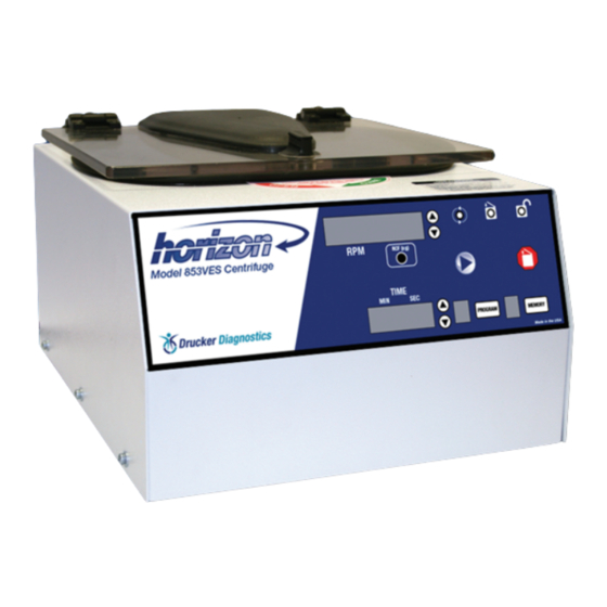
- Page 1 MODEL 853VES Model 853VES Operator’s Manual Laboratory Centrifuge P/N 7711012 Rev. G...
-
Page 2: Table Of Contents
Table of Contents Model Description ..............3 Supplied Equipment ............... 3 Warranty Information ............. 3 Specifications ................. 4 Control Panel / Parts of the Centrifuge ........ 5 Setup Location ................ 6 Initial Setup Procedure ............6 Operation ................7 Tube Holder Configurations 12-Place Horizontal Standard / Performance Plus Rotors .. -
Page 3: Model Description
Also included (not shown): • One (1) 10´ Line Cord • One (1) Operator’s Manual See the next page for a description of optional accessories. WARRANTY: Drucker Diagnostics warranties that this centrifuge is free from defects in workmanship and parts for 2 years. -
Page 4: Specifications
100 mm tube holder 7713040 17 mm x 100 mm 500 to 5,000 RPM 40 to 3,760 xg Contact your authorized dealer or Drucker Diagnostics to order accessories. 75 mm Tube Holder 100 mm Tube Holder Cap 1˝ Cushion Spacer... -
Page 5: Control Panel / Parts Of The Centrifuge
Control Panel / Parts of the Centrifuge Lid Knob Lid Safety Interlock System Control Panel (see below) Cabinet Up/Down RPM Latched Unlocked Change Buttons Running Indicator Indicator Indicator Light Light Light Display Start Button Open / Stop RCF Conversion Button Button Memory Button... -
Page 6: Setup Location
If any problems are found during the initial setup procedure, refer to the troubleshooting section. For further assistance, contact Drucker Diagnostics at +1-814-342-6205 or +1-814-692-7661. 1. Plug the female end of the line cord into the rear of the centrifuge. Plug the male end into an approved electrical outlet. -
Page 7: Operation
Initial Setup Procedure (continued) 9. The ‘RUNNING’ indicator light will illuminate. 10. The test tube carriers will slide up into the horizontal position (horizontal rotor only) and the unit will accelerate to the current set speed. 11. Listen to the sound of the centrifuge. A smooth whirring sound should be heard. If there are any loud or unusual sounds, stop the centrifuge by pressing the ’OPEN / STOP’... -
Page 8: Tube Holder Configurations
Tube Holder Configurations The next two pages will describe proper balancing and tube loading. Use the appropriate section for the rotor installed in your centrifuge. Improper loading can result in damage to the centrifuge or test tube samples. Twelve (12) Place Horizontal Standard and Performance Plus Rotors This rotor is designed to hold up to twelve (12) tube holders. -
Page 9: Control Panel Functions Time Adjustment And Timer Operation
Control Panel Functions Time Adjustment and Timer Operation: The run time may be set from 30 seconds to 99 minutes and 30 seconds. Press the up and down arrow buttons next to the time display to adjust the run time. Adjustments may be made prior to a run or after a run begins. -
Page 10: Braking Rate
Advanced User Settings (continued) Braking Rate: The user may adjust the braking rate from minimum (slowest deceleration, 0) to maximum (quickest deceleration, 9) using the following procedure: 1. While the centrifuge is idle, press the PROGRAM button. 2. Use the UP/DOWN arrow buttons next to the speed display until “BRAKE” is displayed in the speed display. -
Page 11: Memory Locations / Storing And Recalling
Memory Locations / Storing and Recalling The Performance Series centrifuges are capable of storing up to 10 user-defined presets. These memory presets contain all of the settings needed to define a specific run, (run time, speed, acceleration rate, braking rate, etc.). The user can use these memory locations to quickly configure the centrifuge for a specific test type and ensure that the test is run in the same way each time by recalling this same setting. -
Page 12: Care And Preventative Maintenance
If it is necessary to remove the rotor for additional cleaning it is required that a qualified technician remove the outside housing and rotor assembly. Contact Drucker Diagnostics for additional information. Apply cleaning solutions with a towel or cloth. Do not submerge the centrifuge in water or other cleaning solutions as this will cause damage and void your warranty! 6. -
Page 13: Troubleshooting
The centrifuge cannot reach full speed due to a problem with the rotor, an inadequate power supply, or other electrical problems. Press the OPEN/ STOP button to cancel the error and then check the rotor and the line voltage.Contact your authorized dealer or Drucker Diagnostics for further assistance. ERROR / BALANCE The centrifuge has detected an imbalance. -
Page 14: Safety
If the unit is damaged, contact your authorized dealer or Drucker Diagnostics. Calibration and Earth Ground Testing: It is recommended that the top speed, ground continuity and line leakage be tested every two years for continued safe operation. Contact Drucker Diagnostics for further information or testing availability. -
Page 15: Replacement Parts
Contact your authorized dealer or Drucker Diagnostics to order replacement parts or accessories. 200 Shady Lane, Suite 170 • Philipsburg, PA 16866...
Need help?
Do you have a question about the Horizon 853VES and is the answer not in the manual?
Questions and answers