Table of Contents
Advertisement
Quick Links
WARNING: If the information in this manual is not followed exactly, a fire or
explosion may result causing property damage, personal injury or death.
Do not store or use gasoline or other flammable vapors and liquids in the
vicinity of this or any other appliance.
WHAT DO YOU DO IF YOU SMELL GAS
.
Do not try to light any appliance.
.
Do not touch any electrical switch
.
Do not use any phone in your building.
.
Immediately call your gas supplier from a neighbors phone.
Follow the gas suppliers instructions
.
If you cannot reach your gas supplier call the fire department.
Installation and service must be performed by a qualified installer, service
agency or the gas supplier.
REMEMBER: when replacing a part on this appliance, use only spare parts that you can be assured
conform to the safety and performance specification that we require. Do not use reconditioned or copy
IMPORTANT :
IMPORTANT :
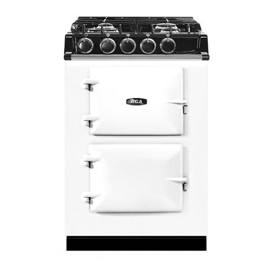
AGA CITY24
(Gas Top Burners)
Installation
Guide
parts that have not been clearly authorised by AGA.
SAVE INSTRUCTIONS FOR FUTURE REFERENCE
CONSERVER CES INSTRUCTIONS POUR REFERENCE FUTURE
For use in USA/Canada
11/15 EINS 517216
Advertisement
Table of Contents

Related Manuals for AGA CITY24 ATC2DFWHT

Summary of Contents for AGA CITY24 ATC2DFWHT
- Page 1 REMEMBER: when replacing a part on this appliance, use only spare parts that you can be assured conform to the safety and performance specification that we require. Do not use reconditioned or copy parts that have not been clearly authorised by AGA. IMPORTANT :...
-
Page 2: Table Of Contents
Health and Safety General Installation Requirements Installation Technical Data Removal From Pallet and Cooker Installation 7 - 8 Range Dimensions - AGA City24 (Gas Top Burners) Clearances 10 - 11 Location Connection to Power Supply Mains Cable Routing Connecting to Gas... -
Page 3: Product Safety
PRODUCT SAFETY MEANING/DESCRIPTION SYMBOL SIGNIFICATION/DESCRIPTION WARNING/CAUTION AVERTISSEMENT An appropriate safety instruction Une consigne de sécurité should be followed or caution to a appropriée doivent être suivies ou potential hazard exists. garde d’un danger potentiel exists. DANGEROUS VOLTAGE TENSION DANGEREUSE To indicate hazards arising from Pour indiquer les dangers dangerous voltages. -
Page 4: General Notes
Regulations. It should be in accordance also with any relevant requirements of the Local Authority. In your own interest and that of safety to comply with the law, all appliances should be installed by an authorized AGA distributor in accordance with the relevant regulations. -
Page 5: Installation
INSTALLATION CAUTION: THIS INSTALLATION MUST CONFORM WITH LOCAL CODES OR, IN THE ABSENCE OF LOCAL CODES, WITH THE NATIONAL FUEL GAS CODE; ANSI Z223.1 / NFPA 54 OR, IN CANADA, THE NATURAL GAS AND PROPANE INSTALLATION CODE CSA B149.1 AND NATIONAL ELECTRICAL CODE ANSI/NFPA 70 (IN CANADA CAN/CGA-B149) AND ONLY USED IN A WELL VENTILATED SPACE. -
Page 6: Technical Data
TECHNICAL DATA GAS TOP BURNERS This appliance is supplied set for Natural Gas (NG) at a pressure of 4” WC. It must be converted to run on LP Gas (Propane) at a pressure of 10” WC. NATURAL GAS L.H.F. R.H.R. L.H.R. -
Page 7: Removal From Pallet And Cooker Installation
REMOVAL FROM PALLET AND COOKER INSTALLATION Removing of transit brackets - Unscrew 4 screws and NOTE: Care must be taken not to trap mains cable. remove brackets, from front and two screws from rear. MAINS CABLE Appliance to be removed from rear of pallet only. - Page 8 REMOVAL FROM PALLET AND COOKER INSTALLATION Appliance can now be pushed back on its wheels into Levelling of appliance - Use ” (13mm) socket to desired position. adjust wheel mechanism for FINE adjustment on both sides at rear of the appliance. NOTE: Care must be taken not to trap mains cable.
-
Page 9: Range Dimensions - Aga City24 (Gas Top Burners)
RANGE DIMENSIONS - AGA CITY24 (GAS TOP BURNERS) Fig. 8 DESN 517229 APPLIANCE WEIGHT (Excludes Packaging) Model: AGA CITY24 (Gas Top Burners) - 474 lbs (215kg) -
Page 10: Clearances
CLEARANCES Side Clearances If you are installing a AGA City24 in a new kitchen or have the opportunity to set the width between kitchen or units, it is advisable to include an additional small gap each side of ” (3mm) to assist with installation and prevent damage when moving the product. - Page 11 Combustible Rear Walls Since this range can be used continuously, please take note of the IMPORTANT INSTRUCTIONS. Where the rear wall is constructed of combustible materials (such as all-timber or stud wall partitions and batoned plasterboard) these will require special wall heat protection measures. Non-combustible insulation board as a protective cladding can be used behind the range of at least ”...
-
Page 12: Location
LOCATION Combustible side wall clearance above the gas top plate shall be greater than 3” (76mm). Surfaces over the top of the range must not be closer than 28” (711mm) and must not exceed 13” (330mm) in depth. The vent slot in the back of the top plate must not be obstructed. Note: It is essential that the supply cable is routed away from any hot surfaces i.e. -
Page 13: Connection To Power Supply
CONNECTION TO THE POWER SUPPLY Electric Shock Hazard Rating Plate is located behind removable plinth, see Fig. 11. Electrical Grounding is required on this appliance. DO NOT connect to the electrical supply until the appliance is permanently grounded. This appliance must be connected to a grounded metallic permanent supply or a grounding connector should be connected to the grounding terminal or wire lead on the appliance. -
Page 14: Mains Cable Routing
MAINS CABLE ROUTING SECURE MAINS CABLE USING ‘P’ CLIPS FOR LEFT HAND OR RIGHT HAND CABLE MANAGEMENT Fig. 10 DESN 516918 POWER CORD 50A/250V 12500W RATED FITTED WITH NEMA 14-50P RIGHT ANGLED PLUG (MATCHING RECEPTACLE 14-50R) UL OR CSA APPROVED Fig. -
Page 15: Connecting To Gas
CONNECTING TO GAS CAUTION: ENSURE THAT THE RANGE IS ISOLATED FROM ELECTRIC SUPPLY. The range can be installed with an approved flexible connection. Supply piping should not be less than ” I/D flexiline. Connection is made to the ” NPT female thread located on the rear right hand side of the range. PRESSURE TEST POINT REGULATOR GAS... -
Page 16: Cooker Stability
COOKER STABILITY A safety chain must be anchored firmly to the wall and cooker to prevent the flexible hose from straining, when the cooker is withdrawn for servicing. When fitting a safety chain refer to Fig. 13. Fig. 13 DESN 517192 If disconnection of the restraining chain is necessary, then ensure restraining chain is re-attached as appliance is relocated in its original position to avoid serious injury or fatality. -
Page 17: Pressure Testing
POSITION OF GAS CONNECTOR ON WALL (located in shaded area) IMPORTANT: THE GAS SUPPLY CONNECTION AT THE WALL MUST NOT PROJECT OUT FROM THE WALL BY MORE THAN 1 ” (45mm), SO THAT IT DOES NOT FOUL WITH THE BACK OF THE RANGE. LOCATION AREA FLEXILINE CONNECTOR... -
Page 18: Assembly Of Burners
ASSEMBLY OF BURNERS FITTING OF BURNER CAP - RAPID AND SEMI-RAPID BURNERS PLACE BURNER CAP OVER RETAINING LUGS, THEN TURN CAP CLOCKWISE TO LOCK INTO POSITION. BURNER CAP RETAINING LUGS Fig. 15A DESN 511617 ASSEMBLY OF RAPID AND SEMI-RAPID BURNERS Fig. -
Page 19: To Adjust Pan Support Level
TO ADJUST PAN SUPPORT LEVEL 1. Loosen retaining nut using ” (8mm) spanner (See Fig. 16). 2. To prevent rocking adjust the pan support foot using ” (2.5mm) allen key. 3. Check pan support is level with opposing pan supports. 4. -
Page 20: Control Knob And Handrail Connection
CONTROL KNOB AND HANDRAIL CONNECTION RIGHT HAND REAR CONTROL KNOB RIGHT HAND FRONT CONTROL KNOB LEFT HAND REAR CONTROL KNOB LEFT HAND FRONT CONTROL KNOB OVEN CONTROL KNOB Fig. 17 DESN 517186 Control Knob and Bezel Location Ensure control knobs and bezels are located onto spindles correctly, as shown in Fig 17. Handrail Location Locate handrail onto spindle, lock into position with grub screws (located on the underside of the bracket). -
Page 21: Wiring Diagram
WIRING DIAGRAM Fig. 18... -
Page 22: Aga City24 (Gas Hob) Checklist
AGA CITY24 (GAS TOP BURNER) CHECKLIST SERIAL No. Tick Box Check pan supports and gas hotplate burners are correctly fitted. Check gas pressure is correct. Check fit of control knobs and bezels. Check hotplate burner ignition. Check oven door seals, adjust door alignment if necessary. - Page 24 For further advice or information contact your local AGA Specialist With AGA Marvel’s policy of continuous product improvement, the Company reserves the right to change specifications and make modifications to the appliance described and illustrated at any time. Supplied by AGA Marvel 1260 E.
Need help?
Do you have a question about the CITY24 ATC2DFWHT and is the answer not in the manual?
Questions and answers