Table of Contents
Advertisement
Quick Links
G
Installation Manual (installer & user)
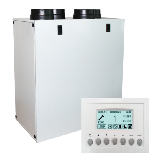
VIGO350A - Heat Recovery Ventilation Unit
The VIGO 350A is continuously running Mechanical Ventilation with Heat
Recovery (MVHR) unit which simultaneously extracts air from wet rooms
while supplying fresh, filtered air to the habitable rooms in a home.
Read this manual carefully before using the product and keep it in a safe
place for reference as necessary.
This product was constructed up to standard and in compliance with
regulations relating to electrical equipment and must be installed by
technically qualified personnel.
The manufacturer assumes no responsibility for damage to persons or property
resulting from failure to observe the instructions contained in this manual.
1 INDEX
1
2
2
2
3
3
4
4
4
4
4
4
5
7
8
8
9
10
11
13
16
17
17
17
18
19
20
1
Advertisement
Table of Contents

Subscribe to Our Youtube Channel
Related Manuals for ELTA FANS VIGO350A


Summary of Contents for ELTA FANS VIGO350A
-
Page 1: Table Of Contents
Installation Manual (installer & user) VIGO350A - Heat Recovery Ventilation Unit The VIGO 350A is continuously running Mechanical Ventilation with Heat Recovery (MVHR) unit which simultaneously extracts air from wet rooms while supplying fresh, filtered air to the habitable rooms in a home. -
Page 2: Precautions
The key to proper, safe and smooth operation of the unit is to read this manual thoroughly, use the unit according to given guidelines and follow all safety requirements. The VIGO350A is supplied with its CTRL-DSP remote multifunction control panel as standard. The package also includes 2 condensation elbows and 2 plugs for the water drainage. -
Page 3: Dimensions And Weight
3.2 Dimensions (mm) and Weight Weight Kg 3.3 Connections LEFT Connections from and to outside are set on the left side of the unit front view DEFAULT RIGHT Connections from and to outside are set on the right side of the unit front view The factory setting is LEFT. -
Page 4: Space Required
Fig. 3.b Connections in RIGHT orientation Intake air from outside Exhaust air to outside Supply air to inside Extract air from inside Winter condensation drainage Summer condensation drainage To set the RIGHT orientation of the machine: • Modify the orientation on the CTRL-DSP (point 7.2 - Installer menu: 3 Machine Orientation). • Replace the ducting connection label on the top of the casing and the water drainage label on the bottom of the casing with those supplied with this installation manual. 3.4 Space required Make sure that enough space is left around the unit to allow easy maintenance (access to filters, terminal box and removal of the side and front inspection panels). -
Page 5: Installation
5.3 Installation The unit must be installed in the following position. It is important that the unit is vertical in order for the condensation drainage to work properly. Fig. 5.a Fig. 5.b Fig. 5.c Fig. 5.d Spirit level Fig. 5.e Fig. - Page 6 Fig. 5.g Individual “dry traps” must be used for each condensate drain on the MVHR. Condensation elbows have an outside diameter of 16mm. Ø125mm Ø125mm Fig. 5.h Fig. 5.i 5.a Prepare the surface where the unit is to be mounted. Make sure that the surface is flat, leveled and that it supports the weight of the unit. Perform the installation in accordance with local rules and regulations. 5.b Drill the holes in the wall.
-
Page 7: Electric Connections
The installation and service of the unit and complete ventilation system must be performed by an authorized installer and in accordance with local rules and regulations. The unit must be earthed. The VIGO350A is wired internally from factory. To connect the the CTRL-DSP to the mother board use a 4pole twisted-pair cable: max length 30m. Figures below show the wiring diagram. -
Page 8: Commissioning
6 COMMISSIONING 6.1 Setting Fan speed The speed of the unit can be adjusted during installation according to required ventilation rate. Figure 6.a below shows performance curves (for supply air and extract air) at different settings of the 0-10V signal to the motors. Airflow and consumption refer to one single motor. Table 6.b indicates the efficiency of the heat exchanger and of the condensation produced in different climatic conditions, to help the installer or the designer of the ventilation system to decide if to connect one or both condensation drainages. -
Page 9: Before Starting The System
Lp dB(A) Lw dB - SOUND POWER OCTAVE BAND 100% Intake Supply Extract Exhaust Breakout Lp dB(A) Lw dB - SOUND POWER OCTAVE BAND Intake Supply Extract Exhaust Breakout Lp dB(A) Lw dB - SOUND POWER OCTAVE BAND Intake Supply Extract Exhaust Breakout... -
Page 10: Operation
7 OPERATION WARNING Make sure that specific warnings and cautions in Chapter 2 “Precautions” are carefully read, understood and applied! Fig. 7.a Temperature probes in LEFT orientation Intake air from outside Exhaust air to outside Supply air to inside Extract air from inside In case of RIGHT orientation, follows instructions as per point 3.3 - Fig. -
Page 11: User Menu On Ctrl-Dsp
When powered on, the CTRL-DSP displays as follows: Fig. 7.c CTRL-DSP operation screen 7.1 User Menu on CTRL-DSP To enter the user menu press OK or ESC. To exit the user menu press ESC or wait for about 60 seconds. Use or to select the menu. User menu Press OK to enter. - Page 12 It allows the selection of boost speed. User menu Press OK to select. 1 Mode Selection Choice NO or YES using or . 2 Boost Press OK to select. Boost speed can be selected only if the Mode selection is 3V or HOLIDAY. 3 Boost Duration Boost function can be activated in these ways: 4 Reset FILTER Alarm...
-
Page 13: Installer Menu On Ctrl-Dsp
7.2 Installer Menu on CTRL-DSP The Installer menu can be selected either by selecting point 6) in the User menu or by holding OK+ESC for about 7 seconds. To exit the installer menu press ESC or wait for about 60 seconds. Use ... - Page 14 It allows to bypass parameters to be set. Installer menu Press OK to enter. 1 Language Use or to choose “Desired Temperature”, “Tmax Free Heating”, “Tmin Free 2 Date/Time Cooling” For definitions see “Bypass” (paragraph 7.3) 3 Machine orientation Press OK to select.
- Page 15 It allows the various speeds to be adjusted. Installer menu Press OK to enter. 6 Heating Threshold Use or to choose speed 1, speed 2, speed 3 or Holiday. 7 Dehumidification Press OK to select. 8 Speed Setting The setting ranges are: 9 Airflow Balancing speed 1: 10% ÷ 80% 10 F7 filter speed 2: 20% ÷ 90% speed 3: 60% ÷ 100% Holiday: 10% ÷ 40%...
-
Page 16: Additional Functionalities
(paragraph 7.1). BYPASS The VIGO350A is equipped with a physical bypass which mitigates the heat exchange when the indoor and outdoor temperature combinations are such that the heat exchange is not recommended. In this case the Bypass icon is activated on the LCD. -
Page 17: Maintenance And Service
8 MAINTENANCE AND SERVICE WARNING Make sure that specific warnings and cautions in Chapter 2 “Precautions” are carefully read, understood and applied! Maintenance can be carried out by the user. Service must be performed only by an authorized installer and in accordance with local rules and regulations. Questions regarding installation, use, maintenance and service of the unit should be answered by your installer or place of purchase! 8.1 Components list... -
Page 18: Maintenance
8.3 Maintenance WARNING Make sure that the mains supply to the unit is disconnected before performing any installation, service, maintenance or electrical work! • Keep the unit surface free from dust. • Clean the filters with a vacuum cleaner following the below illustrations (Fig. 8.b-c-d-e-f-g) when the FILTER signal is displayed on LCD. - Page 19 Fig. 8.h Fig. 8.i Fig. 8.j Fig. 8.l Fig. 8.k Fig. 8.m Fig. 8.n Fig. 8.o Fig. 8.p Fig. 8.q Fig. 8.r Fig. 8.s Fig. 8.t...
-
Page 20: Trouble Shooting
Year Required Maintenance Inspect filters and clean if required every time the alert shows. It is recommended that filters are replaced every year. Clean heat exchanger with vacuum. Clean motors with a vacuum. Ensure condensate drains are working correctly. Inspect filters and clean if required every time the alert shows. It is recommended that filters are replaced every year. Clean heat exchanger with vacuum. - Page 21 ErP Directive - Regulations 1253/2014 - 1254/2014 a) Mark ELTA FANS VIGO350A b) Model c) SEC class c1) SEC warm climates kWh/m2.a -7,3 -2,1 c2) SEC average climates kWh/m2.a -36,9 -30,5 -24,7 c3) SEC cold climates kWh/m2.a -74,1 -66,3 -59,6...
- Page 22 GUARANTEE The product is offered with a five year warranty. First year of warranty covers parts and labour, following this period the warranty covers replacement parts only based on maintenance having being carried out in accordance with our literature and terms and conditions of sale. Proof of Purchase, Periodic inspection and maintenance will be required in the event of any warranty claim.
- Page 23 NOTES...
- Page 24 Elta Fans Limited Building Services 46 Third Avenue Pensnett Trading Estate Kingswinford West Midlands DY6 7US United Kingdom T: +44 (0) 1384 275800 F: +44 (0) 1384 275810 E: bs@eltafans.co.uk 001500 - 04 - 0818...
Need help?
Do you have a question about the VIGO350A and is the answer not in the manual?
Questions and answers