Subscribe to Our Youtube Channel
Summary of Contents for Bogen NQ-E7030
- Page 1 Analog Station Bridge Configuration Guide NQ-E7030 © 2018–2021 Bogen Communications, Inc. All rights reserved. 740-00015G 211012...
-
Page 2: Table Of Contents
Contents Contents ............. . i Configuring the Analog Station Bridge . -
Page 3: Configuring The Analog Station Bridge
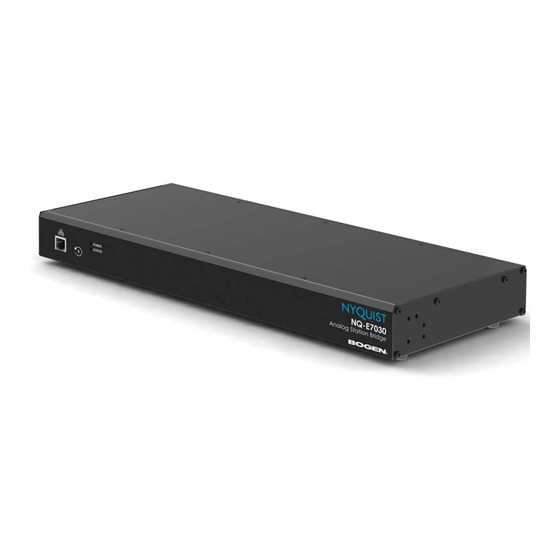
Configuring the Analog Station Bridge The Nyquist Analog Station Bridge (ASB) allows the Nyquist solution to use the existing analog call switch and speaker infrastructure when upgrading from Multicom 2000, Quantum Multicom IP, and third-party intercom systems. When used exclusively as a net- worked component of the Nyquist paging and intercom solution, the Nyquist ASB per- mits a hybrid Internet Protocol (IP)/analog system configuration through use or connection of analog 25V speakers and associated analog call switches (for example,... -
Page 4: Using The Dashboard
Figure 1. Nyquist Appliance Login At the Nyquist Appliance - Login page, enter username and password, and then select Login. The dashboard for the selected appliance appears. Using the Dashboard The ASB dashboard displays information about the ASB, including LEDs and temperature output that provides status of the ASB. - Page 5 Figure 2. Nyquist Analog Station Bridge Dashboard The dashboard displays the following fields: Table 1. Appliance Dashboard Fields Device Type Displays the model of this device. Serial Number Displays the serial number for the device. MAC Address Displays the Media Access Control (MAC) address, which is a unique identifier assigned to network interfaces for communications on the physical network segment.
- Page 6 Table 2. ASB Status Indicators Channel 1/2 Status Provides clipping status for Channel 1 and 2. Clipping is sound distortion that occurs when an amplifier attempts to deliver an output voltage or current that is beyond its maximum capability. If this indicator is green, the channel is not clipping.
- Page 7 Table 2. ASB Status Indicators (Continued) Temperature Provides a snapshot of the amplifier module’s temperature in degrees Celsius during any transition (that is, change state) on the Channel 1, Channel 2, or Protection Status indicators. Note: The ASB’s UI displays the temperature reading from the latest update;...
-
Page 8: Updating Firmware
Updating Firmware When you select Firmware Update from the appliance’s web UI, the Firmware Update page appears. From this page you can determine which Nyquist firmware version the appliance is using and if an update is available. You can also load a firmware release, install the loaded firmware, restore the configuration to factory defaults, and reboot the appliance. -
Page 9: Network Settings Tab Parameters
Prompts the user to specify a firmware file, which will then be loaded (though not installed) onto the appliance. Note: To obtain the firmware file for a specific ver- sion, please contact Bogen Customer Service. Restore Factory Settings Returns the appliance to its original factory con- figuration. - Page 10 Select Save. Figure 4, Network Settings Network settings are described in the following table: Table 5, Network Settings IP Address Identifies the IP address assigned to the appliance. Netmask Identifies the subnetwork subdivision of an IP net- work. Gateway Identifies the address, or route, for the default gate- way.
-
Page 11: Configuration Settings Tab Parameters
Table 5, Network Settings (Continued) TFTP Server Identifies the host name or IP address of the Trivial File Transfer Protocol (TFTP) server. The specified TFTP server can be used to automati- cally set this device’s Configuration settings via the Get Configuration from Server button. If TFTP Server from DHCP (see below) is set to “Yes”, this value will be auto-configured via DHCP option 66, assuming the DHCP server has been configured... - Page 12 To view the Nyquist appliance configuration: On the appliance Web UI’s main page, select Configuration Settings. View the configuration settings. Figure 5. Configuration Settings for ASB Table 6. Configuration Settings Get Configuration from Retrieves configuration settings (i.e., web username, server, and local port) from the TFTP server specified in Server the Network Settings (see Table 1 on page 1).
- Page 13 Table 6. Configuration Settings (Continued) Multicast # Identifies the IP address, port number, cut level (vol- ume), and station list used for the multicast audio stream of one (or more) zones. The following parameters appear for each of the 24 ports associated with the Analog Station Bridge.
- Page 14 Figure 6. Manage Ports To assign a digital call switch to a port: On the appliance Web UI’s main page, select Configuration Settings. Select the Manage button next to the Digital Call Switches column. On the Configuration Settings/Digital Call Switch Management page that appears, drag each Available Digital Call Switch to its port.
-
Page 15: Accessing Log Files
You can assign multiple digital call switches to the same port. If an analog call switch was configured as a station with the type of Digital Call Switch & Speaker. (Refer to the Managing Stations and Zones section of the E7000 Series System Administrator Manual.) When done, select Save All Changes. - Page 16 Available logs are described in the following table. If a log file is empty, however, it will not appear in the drop-down list of available logs. Table 7, Logs Description ampws.log Contains information about protection status and logs protection events with temperature information at the time of event.


Need help?
Do you have a question about the NQ-E7030 and is the answer not in the manual?
Questions and answers