Table of Contents
Advertisement
Quick Links
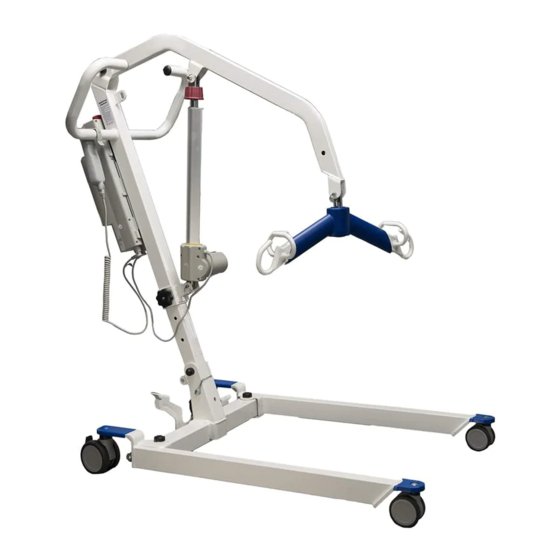
PROTEKT®
FOLDING ELECTRIC PATIENT LIFT
M o d e l : 3 3 4 0 0 P
Ensure the product has been assembled according to the instructions in this
manual. All operators should read and understand the instructions for safe
and proper operation of the patient lift.
TAKE-A-LONG
Folding Position #1 - Flat
Folding Position #2 - Standing
Advertisement
Table of Contents

Related Manuals for Proactive PROTEKT Take-A-Long 33400P


Summary of Contents for Proactive PROTEKT Take-A-Long 33400P
- Page 1 PROTEKT® TAKE-A-LONG FOLDING ELECTRIC PATIENT LIFT M o d e l : 3 3 4 0 0 P Folding Position #1 - Flat Folding Position #2 - Standing Ensure the product has been assembled according to the instructions in this manual.
- Page 2 Thank you for choosing To better serve you, please record the following information for future use: Supplier Name: ___________________________________________ Supplier Telephone: ________________________________________ Product Serial Number: _____________________________________ Date of Purchase: _________________________________________...
-
Page 3: Product Description
Product Description allows the patient to be lifted and transferred safely with minimal physical effort provided by the operator. This is due to it being a full electric lift . With the uses a two point spreader bar. As an added feature this lift is able to be folded and stored away for people with limited space in the home or in the trunk of your car for individuals who like to travel. -
Page 4: Definitions & Symbols
DEFINITIONS & SYMBOLS n this manual the user refers to the patient or resident and may be used interchangeably at different times. Caregiver refers to the operator or person who is assisting with the transfer. Symbols used in this manual and on the product and their meanings: Warning! Failure to heed this warning may Do Not Bleach. -
Page 5: Safety Instructions
Safety Instructions will provide years of service if it is properly maintained as any electric and/or mechanical equipment requires. Please pay careful attention to the following important information regarding the care, maintenance, and operation of the patient lift. Carefully read these instructions before assembling the lift, or attempting to lift a user with the device. - Page 6 WARNING! • NO equipment from its original state. This product is deemed safe to use with equipment may result in serious injury or death. • DO NOT replace any components of the lift without consulting with , and follow proper instruction from when replacing any components.
-
Page 7: Features And Overview
FEATURES & OVERVIEW • Prior to assembly, unpack and inspect all parts from the shipping carton. Contact your dealer immediately if any parts are damaged or missing. • Easy tools are provided to assist with initial set up. To ensure maximum safety, product should not be put into use until all connections are tightened using standard tools. -
Page 8: Specifications And Options
SPECIFICATIONS & OPTIONS Input Voltage 220-240VAC 50Hz / 110-120VAC 60Hz Output Voltage 24 VDC Battery Pack 24 VDC 5AH Lift Control Handset and Panel Protection Class IP54 (Protection against dust and splash of water) Sound Level Under Full Load 16db Sound Level Under No Load 11db Lift Cycles Per Charge... - Page 9 Step 1: Remove folded lift from box Step 2: Secure the stand to the mast. Make sure the tab on the standing bracket sit in the top hole on the mast, and insert the screw to the lower hole as follows. Use the EZ-Tools to tighten the screws.
- Page 10 Step 5: Insert the pin to secure the mast Step 6: Remove the pin that is securing the boom Step 7: Remove lower actuator pin...
- Page 11 Step 8: Move the boom out of the way, and install the lower end of the actuator as follows. It is critical to have the motor part of the actuator to face the same direction as the big arrow as follows. Step 9: Install the upper end of actuator and reinsert the quick release pin to secure it.
- Page 12 Step 10: Installing the Control box on the Lift P E R M I S S I O N O F B E S T C A R E L L C I S P R O H I B I T E D . 1 o f 1 O R A S A W H O L E W I T H O U T T H E W R I T T E N F I N I S H :...
- Page 13 Step 1: Spreader bar at lowest position Step 2: Folding the boom Step 3: Folding the mast Step 4: Standing position...
- Page 14 Operating Instructions • -25°C to +5°C (-13°F to 41°F), and • +5°C to +35°C (41°F to 95°F) at a non-condensing relative humidity 0% to 90% • +35°C to +70°C at a water vapor pressure up to 5 kPa range: • at a temperature range of +5°C to +40°C (+41°F to +104°F) •...
- Page 15 Power Control Unit Overview Emergency Stop Button Up / Down Button Battery Pack Release Handle LCD Display Panel Battery Pack Charger DC In Not Used Additional Battery Pack (Optional) Charging Cradle Actuator (Optional) Hand Control 1. Connect Actuator as shown above. 2.
- Page 16 Pressed In Release LCD Display Panel Signs When the emergency stop button is released, the LCD Display Panel will show one of the four signs below. • The sign will display for 5 seconds. • Then the lift will go into standby mode and the sign disappears. •...
- Page 17 Operating Lift: Using Hand Control LED Indicator Lifting * Green = In Use * Blank = Standby Lowering Operating Lift: Using LCD Display Panel...
- Page 18 Warning! - Battery Low and Charging is Needed If the battery needs to be charged, the LCD Display Panel will show a blinking low battery sign shown on the left either when the emergency stop button is released or when a button on the LCD Display Panel is pressed.
- Page 19 Warning! Use ONLY Proactive Medical slings/products with this REPLACEMENT PARTS LP-TBC2-CRDL ry Charger Cradle ONLY (no plug) f/ Protekt Li /Stand LP-TBC2-CRDL-PK ry Charger Cradle Pack (includes plug) f/ Protekt Li /Stand LP-TC12-BPAK Replacement Ba ry Pack f/ Protekt Li /Stand...
- Page 20 Divided Leg Slings Divided leg design is best suited for high level spinal cord injuries or patients use of bathroom facilities. ITEM # DESCRIPTION 30100P Small Solid divided leg: small 450 lb. weight capacity 30100 Medium Solid divided leg: medium 450 lb. weight capacity 30101 Large Solid divided leg: large 450 lb.
-
Page 21: Safety Loop
2 Point S-Bar 6 Point Hook up A Point 1 Hook up A Hook up B Point 2 Hook up B Insert D through C Insert D th Insert D th Hook up D Point 1 Hook up D Hook up C Point 2 Hook up C 4 Strap Sling... - Page 22 1. User/patient should be in the center of the bed. 2. Position user onto his/her side by rolling user towards you. 3. Roll the sling in half. The handle on the back section should face outward when the 4. Position the sling under the user/patient so the commode aperture aligns with the base of the spine and top of the sling close to the neck.
-
Page 23: Maintenance And Inspection
Maintenance & Inspection • The operator of the lift shall inspect the before each use. Check all bolts for tightness. Make sure the base can be easily widened, and that all lift parts are in place. Make sure that casters can be turned freely, and that caster brakes can be engaged. -
Page 24: Cleaning And Disinfecting
Cleaning and Disinfecting • Use pH-neutral detergents only. • Remove the battery from the controller • Clean lift surfaces, control box and hand control with a damp cloth using pH- neutral detergent. • Remove debris and hair from the casters and make sure the casters can spin and swivel freely. -
Page 25: Troubleshooting Guide
Troubleshooting Guide The following list of encountered problems and solutions will assist you in determining what may be causing your patient lift not to function as designed. If you have a problem occurring which is not listed below please contact your dealer or technical support for help. Do not attempt to repair or replace components or parts on your lift as this may void your warranty or cause further problems that may result in patient injury. - Page 26 Emergency Lowering Mechanism In case of lift failure, please follow the procedures below to safely lower the user. The Emergency Lowering Device is located at the top of the actuator shaft. It is intended for use if the actuator or electronics fail to operate while the patient is suspended in midair. wise continually until the patient has been lowered.
- Page 27 WARRANTY POLICY...
- Page 28 .com...
Need help?
Do you have a question about the PROTEKT Take-A-Long 33400P and is the answer not in the manual?
Questions and answers