Advertisement
Quick Links
Warning! Ignoring the safety and assembly instructions may result in SERIOUS OR FATAL INJURIES
from tip over or the falling of the product and the electrical appliances. Opening the package represents
your undertaking to closely read and follow the instructions. This product is not intended for use in public
places. For Safety Instructions, warranty and further information, go to: www.barkanmounts.com ›
Support › Safety Instructions & Warranty
If you are satisfied with the product, please give us a 5 stars rating on the website you bought it from. If you
are not satisfied please contact us at
TV Size
13"-65"
33cm-165cm
CAUTION
This Mount is intended for use only
with the maximum weight indicated.
Using heavier products might cause injury.
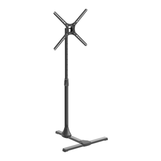
Floor Stand TV Mount
Height
adjustment
For more information: barkanmounts.com
https://www.barkanmounts.com/support
TV Weight
US
EU
80lbs
36kg
Tilt
and we will solve the problem for you.
Page 1
Advertisement

Subscribe to Our Youtube Channel
Related Manuals for Barkan FS310T


Summary of Contents for Barkan FS310T
- Page 1 Page 1 Floor Stand TV Mount Tilt Height adjustment Warning! Ignoring the safety and assembly instructions may result in SERIOUS OR FATAL INJURIES from tip over or the falling of the product and the electrical appliances. Opening the package represents your undertaking to closely read and follow the instructions.
- Page 2 WARNING! Barkan does not take responsibility for the installation and possible tip-over. Ignoring the safety and assembly instructions may result in SERIOUS OR FATAL INJURIES from tip over or the falling of the product and the electrical appliances.
- Page 3 UPOZORNĚNÍ ! Společnost Barkan Mounts Ltd. салмақпен ғана пайдалануға арналған. Көрсетілген není zodpovědná za instalaci a převrácení. ATENÇÃO! A Barkan Mounts Ltd. não oferece ең үлкен салмақтан асатын электр құралдарын орнату Ignorování bezpečnostních a montážních pokynů může garantia de instalação e tombamento.
- Page 4 Page 2 Warnings! Anchor the product to the wall – Tip Over Hazard! using 2 strong cables Collision Hazard – place the product in a position Do not place the product on inclined surfaces, at the edge of a surface or near stairs that will prevent people from colliding with it Adjust the TV tilt angle carefully.
-
Page 5: Main Parts
Page 3 Main Parts Swivel Mechanism TV plate Anchor cables Upper pipe Adaptor Plastic cover Lower pipe Plastic cover Plastic cover Front base Central base... -
Page 6: Included Hardware
Page 4 Included Hardware not to scale inch �� �� �� �� �� �� Required Tools �� ” / 10mm �� �� ” / 8mm ���� �� ” / 8mm ���� �� ” / 3mm No. 2+3 ��... - Page 7 Page 5 Connect the TV plate to the back of the TV Wrong Right Purchase Use the spacers (Z7) in order to longer screws adjust the screws length inside the TV Continue according to your TV mounting hole pattern Page 6 75x75 mm up to 100X100 mm hole pattern Z1/Z2/Z3 NO FORCE...
- Page 8 Page 6 Hole pattern 100x200 mm up to 400x400 mm: Disassemble the screws Connect the 4 adaptors to the TV plate, and reassemble the screws PARTIAL PARTIAL TIGHTENING TIGHTENING Right Right Wrong Wrong...
- Page 9 Page 7 Position the Adaptors according to your TV’s hole pattern Max. 400mm 200mm 400mm For more positioning options turn to page 13 Connect the TV Plate with the Adaptors to the TV in all 4 connection holes Z4/Z5 FULL TIGHTENING NO FORCE Z1/Z2/Z3 Optional...
- Page 10 Page 8 Connect central base (C) to front base (D). Connect the lower pipe (E) to the central base profile (C). Make sure that the cable hole is in the back.
- Page 11 Page 9 Assemble the plastic covers: 1. Slide P10 to the bottom of the lower pipe. 2. Place P11 on the top of the lower pipe. 3. Place P12 on the connections between the beams. 4. Slide the upper pipe into the lower pipe.
- Page 12 Page 10 Weight test Apply force on the upper part of the product and make sure it is assembled properly. 80Lbs/ 36Kg 8 Connect the TV with the Attach the plastic TV plate to the tripod nut-housings (Z9), and then insert the nut (Z8). Make sure that the TV Plate slots are positioned properly...
- Page 13 Page 11 Mark the holes on the wall according to the desired position CONNECTION POINTS Follow the steps according to your wall type �� ” \ 8 mm drill bit Drill with Make sure all holes are drilled ���� �� ”...
- Page 14 Page 12 Connect the cables (T1) to the wall . FULL TIGHTENING Make sure the cables are tighten. You can adjust the length using a wrench. Extend cable �� ” / 8mm ���� Level the TV. SCREEN LEVELING...
- Page 15 Page 13...
Need help?
Do you have a question about the FS310T and is the answer not in the manual?
Questions and answers