Table of Contents
Advertisement
Advertisement
Table of Contents

Related Manuals for Bassi MVD


Summary of Contents for Bassi MVD
- Page 1 BATTERY CHARGER BATTERY CHARGER USER'S MANUAL USER'S MANUAL...
-
Page 2: Safety Precautions
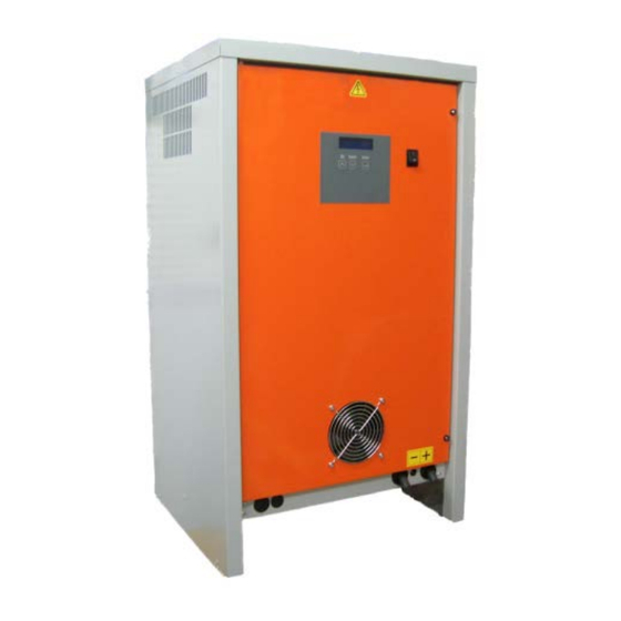
Before to start using the MVD Charger, read these instructions carefully. Installation and Service operations can be done by qualified personnel only. To prevent the risk of electric shock, don't touch uninsulated portions of the MVD- F Charger and the Battery. - Page 3 2. DESCRIPTION The MVD is a series of battery chargers that are based on a new “Hybrid” power conversion system. The two parts that are combined together to compose this “Hybrid” system are: Special isolation transformer, with line frequency multiplication system;...
- Page 4 Language and much more). The charging curve of the MVD charger is based on the parameters that the user entry in a easy menu of a single curve, but instead of applying a defined charge curve to the battery, the charger calculates all the parameters (Currents, Voltage Limits, Maximum Times) according with the Battery Data and the User programming.
-
Page 5: Installation
Battery Charger MVD User's Manual 3. INSTALLATION Conditions of use: • Temperature (operation): from 0°C to 50°C. • Temperature (storage): from –20°C to 60°C. • Relative Humidity: less than 75 %. CONNECTION OF THE AC INPUT The charger must be connected to the AC input using an adequate cable and plug, with disconnect switch and fuses. - Page 6 Battery Charger MVD User's Manual AC INPUT VOLTAGE SELECTION 208/240 or 480/600 VAC The three-phase models may be configured for 208/240 VAC or 480 VAC nominal input voltage. This selection can be done using the apposite terminal block, that is located at the center of the internal panel, between the terminal blocks for the AC input wires and the AC contactor.
-
Page 7: System Check
PRELIMINARY CONTROLS Before to proceed with the programming sequence and before to connect a battery, make sure that the MVD charger has been installed by a qualified electrician, according with the instructions reported in this manual. Before to use the charger, it's necessary to control that the ventilation slots are not obstructed, and that all the safety precautions reported in this manual are respected. -
Page 8: Edit Password
Battery Charger MVD User's Manual USER PROGRAMMING MODE ATTENTION! Before to program the charger, disconnect the battery. This condition is necessary in order to activate the User Programming Mode. Only expert users should modify the settings of the charger. HOW TO ACTIVATE USER PROGRAMMING MODE Press the button DOWN and keep it pressed for 3 seconds •... - Page 9 Battery Charger MVD User's Manual MENU PRG N. 1 – 8 (1-20 OPTIONAL) : PROGRAM SETTING CURVES For each program, it's possible set at maximum 6 different STEP, and for each step it's possible set the TYPE of STEP (current constant, voltage constant, pause cooling), MAXIMUM TIME of the single STEP (0-65350 minute), CURRENT (constant current or minimum limit current ), VOLTAGE (maximum voltage or holding voltage).
- Page 10 Battery Charger MVD User's Manual It's possible to scroll between each programs using the buttons UP/DOWN, and press ENTER to modify or skip each single parameter. ERROR SETTING IN CURVE PARAMETER If the user insert the parameter not correct during the set of internal programs (curves), when...
-
Page 11: Max Voltage
Battery Charger MVD User's Manual PARAMETER : MAX VOLTAGE Programmable values: from 2.40 to 3.00 V/Cell, or DISABLED Default value: 3.00 V/cell VOLTAGE 3.00 V/el NOTES: This parameter sets a maximum limit for the cell voltage. If this limit is reached, the charge is terminated and a specific error message is given. - Page 12 Battery Charger MVD User's Manual PARAMETER : CABLE SECTION Programmable values: from (1 to 250 mm2) or DISABLED. Default value: section of the installed cable. NOTES: The charger can calculate the voltage drop in the cable of the battery, in order to approximate the correct value of the battery voltage.
- Page 13 (OPTIONAL) PARAMETER : WIRED NET / TEST WIRELESS / LOCAL USB NOTE: This is an advanced function, described on the MVD “ADVANCED PROGRAMMING MANUAL”. It's used when the charger is equipped with a Communication Card to the fleet management system DoctorFleet.com, or when it's equipped with an Expanded Data-Logger Card with USB connection.
-
Page 14: Program Examples
Battery Charger MVD User's Manual 5. PROGRAM EXAMPLES PROGRAM CURVE : IUIa 480m I=18%Ah V=2.40 V 240m I=5%Ah V=2.40 V 180m I=5%Ah V=2.65 V T= DIS. I= DIS. V= DIS. T= DIS. I=DIS. V=DIS. T= DIS. I=DIS. V=DIS. Using this Program for the follow battery: reading battery voltage 24.7 V 24.7 V... - Page 15 Battery Charger MVD User's Manual In the first step A (1.A) , the charger workes in current costant way (I=K) for the maximum time of (480 minutes) with a current of (18%Ah --> [500 Ah] 5*18 = 90 Amp), and if the battery voltage reache (2.40 V/Cell) before the end of the time, the charger will go to next step.
- Page 16 Battery Charger MVD User's Manual PROGRAM CURVE : IU1 U2 200m I=25%Ah V=2.40 V 240m I=3%Ah V=2.40 V T=FULL I=DIS V=2.25 V T= DIS. I= DIS. V= DIS. T= DIS. I= DIS. V= DIS. T= DIS. I= DIS. V= DIS.
- Page 17 Battery Charger MVD User's Manual In the second step B (3.B) , the charger workes in voltage costant way (V=K) for the maximum time of (240 minutes) and compensation the current for hold the battery to (2.40 V/Cell), and if the current go down until (3%Ah -->...
- Page 18 Battery Charger MVD User's Manual PROGRAM CURVE : I1 + I2 +I3 + I4 + I5 +I6 I=15%Ah V=DIS 120m I=20%Ah V=DIS 180m I=25%Ah V=2.40 240m I=15%Ah V=2.60 V 120m I=10%Ah V=DIS 120m I=5%Ah V=DIS Using this Program for the follow battery: reading battery voltage 0.0 V 0.0 V...
- Page 19 Battery Charger MVD User's Manual of (240 minutes) with a current of (15%Ah --> [600 Ah] 6*15 = 90 Amp), and if the battery voltage reache (2.60 V/Cell) before the end of the time, the charger will go to next step.
- Page 20 In the first step A (6.A) , the charger workes in voltage costant way (V=K) for ever (FULL) and compensation the current for hold the battery to (2.25 V/Cell). During this step not exist any limits of current and MVD can work until the maximum current. Steps (6.B), … , (6.F) are empty.
- Page 21 Battery Charger MVD User's Manual PROGRAM CURVE : Voltage Refresh - Limited current 12.A I=5%Ah V=2.25 12.B T= FULL I=DIS. V=2.25 12.C T= DIS. I= DIS. V= DIS. ….. 12.F T= DIS. I= DIS. V= DIS. Using this Program for the follow battery: reading battery voltage 80.0 V 80.0 V...
-
Page 22: Operation
Battery Charger MVD User's Manual 6. OPERATION START OF THE CHARGE Connect the Battery to the charger, using a connector of adequate size. When the battery is correctly connected, the charger visualizes the following message: XX.X V XXXX Ah EL= XX PROG.XX... -
Page 23: Battery Voltage
A xxx Ah x.x t The MVD-F Charger performs an IEI charge cycle, and the management of the charging curve is totally automatic. While the charge is in progress, it's always possible to scroll between different menu pages, using the buttons UP/DOWN: CHARGE STATE •... -
Page 24: Cycle Complete
RESTART AFTER POWER SUPPLY OFF REVERSE POLARITY PROTECTION The MVD chargers are equipped with an active protection against the connection of batteries with Reverse Polarity. If a battery with reverse polarity is connected, the charger remains in a safe Stand-By mode. - Page 25 Eventually, the charge can be restarted, by pressing the button UP for 5 seconds. ANTI ARCING PROTECTION The MVD charger is equipped with a built-in Anti-Arcing protection. In order to activate this function, it's necessary to add an optional wire loop, using a battery connector equipped with Auxiliary Pins.
- Page 26 Battery Charger MVD User's Manual 7. BATTERY DESULPHATION The Battery Desulphation/Recovery function is useful when batteries are overdischarged, or they have been left unused for a long time. The Desulphation/Recovery cycle can be activated at any moment, while a battery is connected, by pushing the button ENTER and keeping it pressed for 3 seconds.
-
Page 27: Led State
Battery Charger MVD User's Manual 8. LED STATE The MVD during the charge, the display will show the message: xx.x V xxx A xxx Ah x.x t CHARGE CYCLE for more info. see charapter The state of the leds are the follow. - Page 28 Blink second green light. And if the power of the charger go up its maximum limit, the MVD auto limit the current and the third led is fixed YELLOW STEP PAUSE / COOLING [PAU] Blink first and second green lights.
- Page 29 Fix first and second green lights. And if the power of the charger go up its maximum limit, the MVD auto limit the current and the third led is fixed YELLOW CYCLE COMPLETE At the end of Cycles the charger waits for the disconnection of the charger. Use the UP and DOWN pushbuttons to scroll the menu.
- Page 30 Battery Charger MVD User's Manual MANUAL STOP / MANUAL RESTART At all times it's possible to STOP the charge process pressing and keeping pressed the UP pushbutton until the display shows: MANUAL STOP Releasing the pushbutton the charge stops and the display shows: 25.3 V...
- Page 31 User's Manual 9. HISTORY LOG (OPTIONAL) The internal memory of the MVD charger contains a log of the last 250 charge cycles. The most significative parameters can be visualized on the display of the charger, while the complete history log can be accessed and downloaded through DoctorFleet.com management system.
- Page 32 Battery Charger MVD User's Manual PAGE B End Date and Time HH.MM AHRET Where: End Date and Time = Date and Time of the TERMINATION of the charge TT = Charge Termination Code (see next paragraph) HH.MM= Total charge time...
- Page 33 Battery Charger MVD User's Manual GROUP 3: BATTERY DISCONNECTED The battery has been disconnected during cooling phase. Desulphation cycle NOT completed. The battery has been immediately disconnected, at the beginning of the Desulphation cycle Desulphation cycle NOT completed. The battery has been immediately disconnected, before to complete the programming of the Desulphation cycle.
- Page 34 Battery Charger MVD User's Manual Emergengy Stop! Battery voltage exceeded maximum programmed value during the constant voltage phase. Emergengy Stop! Battery temperature exceeded maximum programmed value during the constant voltage phase. Emergengy Stop! Battery temperature exceeded maximum programmed value during the constant current phase.
Need help?
Do you have a question about the MVD and is the answer not in the manual?
Questions and answers