Table of Contents
Advertisement
Quick Links
Advertisement
Table of Contents

Related Manuals for TECHNIMOUNT SAFETY ARM SYSTEM 500

Summary of Contents for TECHNIMOUNT SAFETY ARM SYSTEM 500
- Page 1 SAFETY ARM SYSTEM USER GUIDE...
-
Page 2: Copyright
Copyright 2022 Technimount E.M.S. Holding Inc. (Technimount), an affiliated company of Technologies CGC Inc. All Rights Reserved. No part of this publication may be reproduced, transmitted, transcribed, stored in a retrieval system, or translated into any language in any form or by any means without the written permission of Technimount or its affiliate companies. -
Page 3: Contact Information
T + 1 581.700.6613 TF + 1 888.639.2758 NOTE: For any issues with your Technimount product, its components, or for any technical questions during the installation or maintenance, please send an Email to techsupport@technimount.com Please have the serial number of your Technimount product available (as shown on picture below) when calling Technimount Customer Service or Technical Support. -
Page 4: Table Of Contents
Installing the Standard Surface Base onto the Safety Arm System Upper Plate ..........39 OPERATION CAUTION AND WARNING ....................... 41 OPERATION GUIDE .............................. 42 General Operating Guidelines ............................42 Recommended Lifting Techniques ........................42 Recommended Handling Positions ........................43 Operating the Safety Arm System ..........................44 Lowering the Safety Arm.............................45 SAS UG 202205-01 www.technimount.com... - Page 5 Prior to 30 Days ..............................57 Prior to 45 Days ..............................57 Prior to 60 Days ..............................57 Return Authorization ..............................57 Damaged Merchandise ..............................58 Claim Process ................................58 Required Information ............................58 Findings and Conclusion .............................58 Questions about our Policy ............................58 SAE CERTIFICATION ............................. 59 www.technimount.com SAS UG 202205-01...
-
Page 6: Introduction
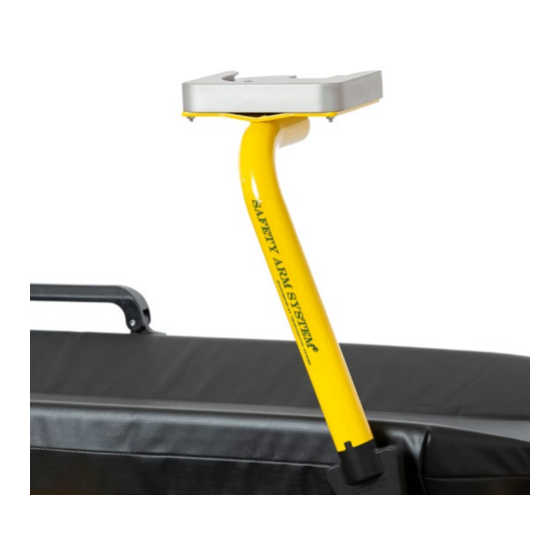
INTENDED USE OF THE PRODUCT The Safety Arm System 500 is a secure mounting system for medical devices, designed to be installed on a stretcher (Stryker Stretchers MX-PRO and Power-PRO models). The mount is intended to support and transport medical equipment during a medical intervention of a traumatized, an ambulatory or non-ambulatory patient (including infants, children and adults). -
Page 7: Symbols And Definitions
Introduction SYMBOLS AND DEFINITIONS SYMBOL DESCRIPTION Caution, special attention is required. Consult accompanying documents Safe working load symbol and Load balance symbol Pinch Point Return To Table of Contents www.technimount.com SAS UG 202205-01... -
Page 8: Warning / Caution / Note
This includes special care necessary for the safe and effective use of the device to avoid damage that may occur as a result of use or misuse. NOTE Provides special information about the product. Return To Table of Contents SAS UG 202205-01 www.technimount.com... -
Page 9: Identification Of Components
The fixed safety pin is identified by the red round handle mechanism used for locking the arm in the upper position. a) Side Lock Pin Aperture b) Safety Pin with red handle CLAMP BLOCK WITH SAFETY PIN Return To Table of Contents www.technimount.com SAS UG 202205-01... -
Page 10: Clamp Block
SAFETY ARM BASE MOUNT (UPPER PLATE) AND B) HARDWARE FOR INSTALLATION OF THE BASE TO THE PLATE YELLOW SAFETY ARM Return To Table of Contents SAS UG 202205-01 www.technimount.com... -
Page 11: Hardware Kit For The Safety Arm
INSTALLATION RELATED TO THE STRYKER POWERLOAD STRETCHER 9 The spacer block is the shim installed under the “V” bracket on the cot/stretcher frame when a power load system is installed with the cot/stretcher. This bracket is NOT a Technimount part. Return To Table of Contents www.technimount.com... -
Page 12: Technical Specifications
• SAE J3043 (26 G) Mounting System Retained on Stretcher with Clamp Block, Installation Lock Pin and Red Handle Safety Pin. Compatible with Technimount’s: Transportation Compatibility Systems • Standard Surface Base • Bracket Pro Serie® Product Line with a Standard Bottom Disc •... - Page 13 530-10-MXPR - Clamp Block (Stryker MX-PRO Right Side) • 530-10-MXPR-LFS - Clamp Block (Stryker MX-PRO Left Side) Contact Technimount EMS for more information or for other Other Models and Configuration Options options at customerservice@technimount.com Return To Table of Contents www.technimount.com...
-
Page 14: Notice
Introduction NOTICE The Safety Arm System is designed to comply with SAE J3043 safety standards. Please contact Technimount Customer Service Department at (customerservice@technimount.com) for more information. Technimount E.M.S. Holding Inc. Regulatory Affairs 3770, Jean Marchand Street, Suite 100-C Quebec City (QC) G2C 1Y6 Canada T + 1 581.700.6613... -
Page 15: Product Information
Product Information PRODUCT ILLUSTRATION WITH OTHER EQUIPMENT ON STRETCHER Standard Surface Base to Install Medical Devices with Technimount’s Mounting Systems that have Standard Bottom Discs Arm Surface Plate to Install the Standard IV Pole Surface Base Movable Arm Section 90° Inclination in... -
Page 16: Installation Overview
Product Information PRODUCT ILLUSTRATION (CONTINUED) INSTALLATION OVERVIEW Upper Position Locked Position for Transportation SAFETY ARM SYSTEM INSTALLED ON COT Return To Table of Contents SAS UG 202205-01 www.technimount.com... -
Page 17: Summary Of Safety Precautions
9 It is the responsibility of the operator of the cot/stretcher to ensure that the Safety Arm System being used with Technimount products meets the installation specifications. Injury may result if non-compatible products are used with Technimount products. - Page 18 It may result in damage to the arm and/or result in injury to the patient or operator. 9 Do not place any additional equipment or objects on the arm, other than the approved Technimount device bracket for medical devices.
- Page 19 Technimount continually seeks advancements in product design and quality. Therefore, while this manual contains the most current product information available at the time of printing, there may be minor discrepancies between your arm system and this user guide. If you have any questions, please contact Technimount Customer Service or Technical Support at +1.581.700.6613.
-
Page 20: Installation Guide
9 During the installation process, Technimount recommends the use of Blue Loctite 2400 to avoid premature loose- ning of screws during normal use. Put a few drops of Blue Loctite on each screw prior to installation. -
Page 21: Cot/Stretcher Orientation Diagram
Installation Guide COT/STRETCHER ORIENTATION DIAGRAM Patient Head Patient Right Patient Left Installation Installation Location Location Patient Right Patient Left Patient Foot End Return To Table of Contents www.technimount.com SAS UG 202205-01... -
Page 22: Preparing The Cot/Stretcher For Installation
9 If the cot/stretcher has an IV pole located on the side you want to install the Safety Arm System, you will need to remove the IV Pole. 9 To keep the IV pole on the same side as the cot/stretcher, you will need to install a Technimount IV Pro Adapter (Refer to Replacement Parts Table). - Page 23 1. To access screws that hold the IV pole and the holder, lift the IV pole to its upper position. 2. Remove all four (4) screws. 3. Remove IV Pole and holder. 4. Replace all four (4) screws. Return To Table of Contents www.technimount.com SAS UG 202205-01...
- Page 24 5. The IV pole can be installed on the other side of the cot/stretcher, utilizing the same bracket/hol- der. 6. If the IV Pole is not needed, store for later use. Return To Table of Contents SAS UG 202205-01 www.technimount.com...
-
Page 25: Safety Arm System Installation
9 The location for the installation of the clamp block is the same on patient right or left sides. Patient Head Patient Head Patient Right Patient Left Installation Installation Patient Foot End Patient Patient Left Right MODEL 500 - INSTALLATION POSITION ON PATIENT RIGHT AND LEFT SIDES Return To Table of Contents www.technimount.com SAS UG 202205-01... -
Page 26: Position On The Cot/Stretcher (Continued)
Patient Head Patient Patient Patient Patient Right Left Right Left Patient Foot End POSITION OF SAFETY ARM SYSTEM - PATIENT PATIENT RIGHT SAFETY ARM SYSTEM INSTALLED AND IN RIGHT UPPER POSITION (LOCKED) Return To Table of Contents SAS UG 202205-01 www.technimount.com... -
Page 27: Installing The Clamp Block (Patient Right)
INSTALLING THE CLAMP BLOCK (PATIENT RIGHT) NOTE 9 During the installation process, Technimount recommends the use of Blue Loctite 2400 to avoid premature loose- ning of screws during normal use. Put a few drops of Blue Loctite on each screw prior to installation. - Page 28 3/16 in Allen key. 7. Use the part with the fixed red handle to place vertically on the inside of the cot/stretcher frame. Return To Table of Contents SAS UG 202205-01 www.technimount.com...
- Page 29 10. Add a couple of drops of blue Loctite 2400 to the screws before installation. 11. Tighten screws, while alternating screwheads. 12. Tighten the screws located on the opposite side of the stretcher. Return To Table of Contents www.technimount.com SAS UG 202205-01...
- Page 30 15. Tighten all four (4) stainless steel hexagon socket pan head screws, while alternating with all four (4) screws. 16. Once the clamp block is properly installed, you are ready to install the Safety Arm into the clamp block. Return To Table of Contents SAS UG 202205-01 www.technimount.com...
-
Page 31: Preparing The Iv Pro Adapter Plate
4. IV Pro Adapter plate with the 2 blocks installed. Return To Table of Contents Return To Table of Contents www.technimount.com SAS UG 202205-01... -
Page 32: Installing The Micro Base On The Iv Pro Adapter Plate
Base onto the IV Pro Adapter plate. 2. Align with the five (5) screw holes. 3. Add a couple of drops of blue Loctite to the screws before installation. 4. Tighten screws, while alternating screwheads. Return To Table of Contents SAS UG 202205-01 www.technimount.com... -
Page 33: Installing The Iv Pro Adapter
SAFETY ARM SYSTEM INSTALLATION (CONTINUED) INSTALLING THE IV PRO ADAPTER NOTE 9 During the installation process, Technimount System recommends the use of Loctite 2400 (Blue) to avoid prema- ture loosening of screws during normal use. 1. Identify the location on the cot/stretcher where you need to install the IV Pro Adapter. - Page 34 Safety Pin open, turn the red round han- dle counter clockwise, to unscrew and remove the red round handle. 4. Remove the red round handle. 5. Locate all 4 screw holes on the stretcher frame. Return To Table of Contents SAS UG 202205-01 www.technimount.com...
- Page 35 11. Put a few drops of blue Loctite onto the screw before replacing the red round handle. This will prevent premature loosening of the screws du- ring normal use. 12. Replace the red round handle while turning clo- ckwise. Return To Table of Contents www.technimount.com SAS UG 202205-01...
-
Page 36: Installing The Iv Pole And Holder Onto The Iv Pro Adapter
1. Locate the 2 blocks on either side of the IV Pro Adapter plate. 2. Install the IV Pro Holder onto the block located near the Clamp Block. 3. Align with the two (2) screw holes. 4. Tighten both screws. Return To Table of Contents SAS UG 202205-01 www.technimount.com... - Page 37 7. Use the same screws provided with the IV Pole or similar screws provided, with same threads and length. 8. Tighten both screws. 9. When not in use, lower the IV pole and clip it into its holder. Return To Table of Contents www.technimount.com SAS UG 202205-01...
-
Page 38: Installing The Safety Arm Into The Clamp Block
(Locked). WARNING Failure to insert the side safety pin properly may result in injury to the patient or operator and/or damage to the cot/stretcher and/or the medical equipment. Return To Table of Contents SAS UG 202205-01 www.technimount.com... -
Page 39: Installing The Standard Surface Base Onto The Safety Arm System Upper Plate
The base can be installed in 2 different positions, according to desired configuration and protocol. Can be turned in the other direction, (180°). Return To Table of Contents www.technimount.com SAS UG 202205-01... - Page 40 Philips screwdriver. 6. Tighten all four (4) screws of the Standard Sur- face Base at the front, and at the back with the Philips screwdriver and the mechanical wrench SAE 3/8 in. Return To Table of Contents SAS UG 202205-01 www.technimount.com...
-
Page 41: Operation Caution And Warning
9 Always pull and hold the locking safety pin (red handle) until it reaches the final position (up (locked) or down (unlocked)) so the arm doesn’t fall during transport. Failing to do so can cause injury to the operator or patient. Return To Table of Contents www.technimount.com SAS UG 202205-01... -
Page 42: Operation Guide
4. Avoid twisting 5. Always operate the arm as described in this user guide 6. Always secure the movement of the equipment by holding the arm firmly Return To Table of Contents SAS UG 202205-01 www.technimount.com... -
Page 43: Recommended Handling Positions
Improper positioning of the arm can cause premature damage or cause improper functioning of the Safety Arm System. Return To Table of Contents www.technimount.com SAS UG 202205-01... -
Page 44: Operating The Safety Arm System
9 Ensure proper hand placement on the tubular pole or surface plate. Hands should be clear of the black clamp block and arm pivot points while loading and unloading the medical equipment or whenever changing height of the arm with two or more operators. Return To Table of Contents SAS UG 202205-01 www.technimount.com... -
Page 45: Lowering The Safety Arm
9 Always pull and hold the safety pin (red handle) until it reaches the final upper position (locked) or down (un- locked). Failure to pull the fixed safety pin (red handle) when repositioning the arm may cause damage to the Arm or locking mechanism. Return To Table of Contents www.technimount.com SAS UG 202205-01... -
Page 46: Raising The Safety Arm
9 Always pull and hold the safety pin (red handle) until it reaches the final upper position (locked) or down (un- locked). Failure to pull the safety pin (red handle) when repositioning the arm may cause damage to the Arm or locking mechanism. Return To Table of Contents SAS UG 202205-01 www.technimount.com... -
Page 47: Removing The Safety Arm
3. Remove the fixed lock pin by pulling outwards. 4. Pull and hold the Safety Pin (red round handle). Return To Table of Contents www.technimount.com SAS UG 202205-01... - Page 48 5. While Securely holding the arm, pull upward in order to disengage the triangle head from the clamp block. 6. Once the Safety Arm is removed, put the lock pin back into the clamp block. Return To Table of Contents SAS UG 202205-01 www.technimount.com...
-
Page 49: Safety Arm System Options
Safety Arm System Options STRYKER POWER-PRO OPTIONS Some exceptions may apply for the Power-PRO stretcher. Please confirm with Customer Service at customerservice@ technimount.com prior to placing your order. DESCRIPTION OPTION PART NUMBER Tubular Arm with Triangular Base – Patient Right Installation Yellow-Powder-... -
Page 50: Maintenance Guide
Suggested cleaners for the Safety Arm System surfaces and clamp box: 9 Quaternary Cleaners (active ingredient - ammonium chloride) 9 Phenolic Cleaners (active ingredient - o-phenyl phenol) 9 Chlorinated Bleach Solution (3.25% - less than 1-part bleach to 100 parts water) Return To Table of Contents SAS UG 202205-01 www.technimount.com... -
Page 51: Removal Of Iodine Compounds
PREVENTIVE MAINTENANCE A preventive and regular maintenance program should be established for all Technimount equipment. Preventive maintenance may be required more frequently based on the usage level of the product. The Safety Arm System requires regular preventive maintenance. -
Page 52: Inspection Process And Schedule
If you are unsure as to how to perform these maintenance inspections or at what interval to perform these inspections, please contact your Technical Support Team at techsupport@technimount.com. Check each routine and replace damaged or worn out parts if necessary. -
Page 53: Inspection And Maintenance Record
Maintenance Guide INSPECTION AND MAINTENANCE RECORD PREVENTIVE MAINTENANCE DATE TIME PERFORMED Return To Table of Contents www.technimount.com SAS UG 202205-01... -
Page 54: Training Record
Maintenance Guide TRAINING RECORD TRAINING DATE TRAINING METHOD USER GUIDE, IN-SERVICE, BASIC TRAINING TRAINEE NAME IN-CLASS, TRAINING UPDATE ETC. Return To Table of Contents SAS UG 202205-01 www.technimount.com... -
Page 55: Replacement Parts
The parts and accessories listed are all currently available for purchase. Some of the parts identified on the assembly drawing parts in this user guide may not be individually available for purchase. Please call Technimount Customer Service at +1.581-998-9820 or at customerservice@technimount.com... -
Page 56: Warranty
Technimount products are intended to retain a medical device in place in the case of a single crash impact. A Technimount product must NOT be used again if it was involved in a crash. The product MUST be replaced. If the Purchaser uses a Technimount product following a crash, it is at the Purchaser’s own risk and Technimount will not be... -
Page 57: Return Policy
For any manufacturing defect, refer to the conditions of the Warranty Policy. PRIOR TO 30 DAYS ▪ Product must be undamaged and in its original packaging The product return request must be provided in writing and it must be approved by TECHNIMOUNT prior to retur- ▪ ning the product ▪... -
Page 58: Damaged Merchandise
Claim will be limited in amount to the actual replacement cost. In the event that this information is not received by TECHNIMOUNT within the fifteen (15) day period following the delivery of the merchandise, or the damage was not noted on the delivery receipt at the time of receipt, the customer will be responsible for payment of the original invoice in full. -
Page 59: Sae Certification
SAE Certification Return To Table of Contents www.technimount.com SAS UG 202205-01... - Page 60 Technimount E.M.S. Holding Inc. 3770 Jean-Marchand Street, Suite 100-C Quebec (QC) G2C 1Y6 Canada T + 1 581.700.6613 TF + 1 888.639.2758 technimount.com info@technimount.com © 2022 Technimount E.M.S. Holding Inc. - All Rights Reserved Printed in Canada...
- Page 62 SAFETY ARM SYSTEM USER GUIDE...
Need help?
Do you have a question about the SAFETY ARM SYSTEM 500 and is the answer not in the manual?
Questions and answers