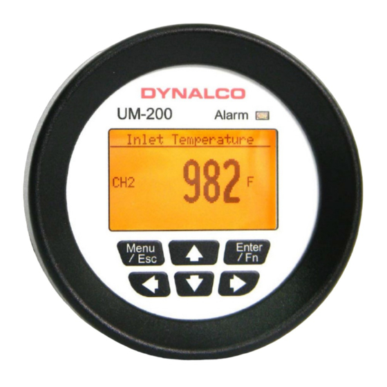
Summary of Contents for Dynalco UM-200
- Page 1 3211 Fruitland Ave Los Angeles, CA 90058 UM-200 2-Channel Monitor Version 2 Installation and Operation Manual Rev. D P/N145F-13019 (c) Copyright 2013, Dynalco Controls All Rights Reserved Published: December 3, 2013...
-
Page 3: Additional Features
/ shutdown output. Basic operation: The UM-200 will be in “stopped” mode until a run indication is sensed. This is selectable as either a contact closure or magnetic pickup input. Once “running” mode is sensed, the UM- 200 will read both inputs at a rate of 100 msec per channel. - Page 4 Installation The UM-200 is designed to be panel mounted. The dimensions are shown below. The UM-200 has a bracket for securing into the panel.
-
Page 5: Terminal Connections
Terminal Connections All connections are made to terminals on the back of the unit. Terminal screws to be tightened to 8 inch-pounds torque. See page 10 for complete wiring information. - Page 6 Programming Overview All programming is accomplished through the front keypad. Below is a brief description of each key. Press to enter or exit the configuration screens Press to enter or accept values Select up Select down Go back one screen Select and advance to next screen...
- Page 7 6) Setting either latching or non-latching for output trip Programming Instructions Important: The UM-200 must first be programmed prior to operation. When first powering up the unit, the display will first indicate the firmware version and then go to the operational mode.
- Page 8 Configuration of “Run Signal” Using the arrows on the keypad, select the “Run Signal” icon. There are (3) run types available. The definitions are as follows: None: No run indication required. Monitoring is always active. RPM: Monitoring is active when signal received from magnetic pickup. Digital: Monitoring is active when contact closure (connection to ground) is sensed.
- Page 10 Alarm / Shutdown Output The UM-200 will alarm when either channel value or differential value is above or below limits as specified. Alarms can be configured as either latching or non-latching. If an alarm condition is met, the red LED on the front panel will blink and the digital output (if enabled) will trip.
- Page 11 Additional instructions for current users of Dynalco models TID-110 or STM-110 series temperature monitors The following products may be upgraded to the model UM-200 monitor: TID110-11 J type thermocouple (displays in DegF) TID110-12 J type thermocouple (displays in DegC) TID110-13...

Need help?
Do you have a question about the UM-200 and is the answer not in the manual?
Questions and answers