Table of Contents
Advertisement
Quick Links
Advertisement
Table of Contents

Subscribe to Our Youtube Channel
Related Manuals for Kanomax 6333


Summary of Contents for Kanomax 6333
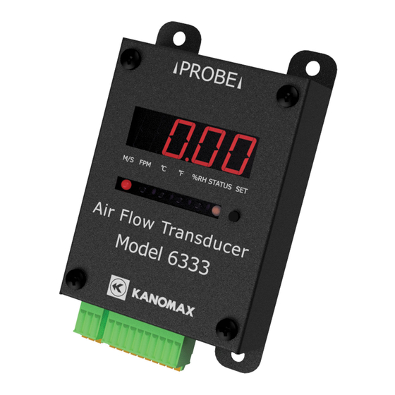
- Page 1 Air Flow Transducer Model 6333 User’s Manual...
- Page 3 Air flow/temperature probe independent type) Omni-directional air velocity probe VT 0975-21 Air flow/temperature probe Omni-directional air velocity probe VTH 0975-31 Air flow/temperature/humidity probe Standard cable (0.5 m) 1580-30 For 6333 probe-to-probe connection Standard cable (2.0 m) 1580-31 For 6333 probe-to-probe connection...
- Page 4 For 6333 probe-to-probe connection Standard cable (5.0 m) 1580-32 For 6333 probe-to-probe connection Standard cable (10.0 m) 1580-33 Standard cable (20.0 m) 1580-34 For 6333 probe-to-probe connection Standard cable (40.0 m) 1580-35 For 6333 probe-to-probe connection...
-
Page 5: Important Safety Information
Important Safety Information The symbols for the warnings used in this manual are defined below. Description of Symbols Warning: To Prevent Serious Injury or Death Warnings in this classification indicate risks that may result in serious injury or death if not observed. CAUTION: To Prevent Damage to the Product Warnings in this classification indicate risks that may result in damage to the product and which may void the product... - Page 6 Warning Always keep the probe away from areas where flammable gas is present. Failure to do so may cause fire and/or explosion because the Forbidden probe heats. Never touch the air velocity element. Direct touch to the element could cause burn injuries. Touching to the element may also cause damage to the Do Not element.
- Page 7 Do not apply an excessive force to the sensor. If the sensor is deformed, not only maintaining the accuracy is impossible but also the element may be broken. Forbidden Do not use or keep the instrument in hot, humid, or dusty environment.
- Page 8 Do not allow static electrical discharge to the instrument. Failure to observe the above may affect the measurement Forbidden value and cause damage to the instrument circuit. Electrostatic-sensitive devices Regularly check that the tip of the probe is clean. Dust and/or foreign substances adhered to the air flow element can hinder the accurate measurement.
-
Page 9: Table Of Contents
Table of Contents List of Components ..........................i Important Safety Information ......................iii Table of Contents ..........................vii 1. Product Appearance .......................... 8 ....................... 8 1-1.Part Names and Functions ........................... 9 1-2.External Dimension ..................10 1-3. Mounting/Removing DIN Rail Fixing Base 2. -
Page 10: Product Appearance
1. Product Appearance 1-1.Part Names and Functions ■ Probe connector Connect the probe ■ Changeover button Switches the unit of ■ measurement (air Indicating display velocity/temperature/humidity). Indicates measured values ※Only the unit of measurement that the probe supports will be displayed. -
Page 11: External Dimension
1-2.External Dimension ※The dividing terminal block is excluded. -
Page 12: Mounting/Removing Din Rail Fixing Base
1-3. Mounting/Removing DIN Rail Fixing Base To attach the Air Flow Transducer to the DIN rail, use the DIN rail fixing base. Mount the DIN rail fixing base on the back of the Air Flow Transducer with the provided screws (6 EA). -
Page 13: How To Use
2. How to Use 2-1.Basic Usage Standard cable Probe 6333 main unit AC adaoter Output cable RS485 cable Configure the instrument in the following sequence to use. 1.Situate the probe in a measurement place and connect the probe to the instrument. -
Page 14: Mounting/Removing The Probe
When the instrument is used in a high humidity environment for long hours or in the abrupt temperature variation environment, the instrument can show higher measured humidity value than the actual one. If condensation occurs, leave the probe in a place of 40%RH or lower for 24 hours to dry 2-2.Mounting/Removing the Probe To mount the probe, face the probe connector toward the instrument connector as shown... -
Page 15: Connecting The Cable To The Terminal Block
2-3.Connecting the Cable to the Terminal Block Once the terminal block is separated, the cable can be connected easily to the terminal block. You can remove the terminal block with the fingers. This terminal block can be divided into two terminal blocks, 3P and 10P. ... -
Page 16: Connecting Power Source
2-4.Connecting Power Source There are two methods to supply power to the instrument. 1. Supply from the AC adapter Connect the supplied AC adapter to the AC adapter connector to supply power. Do not use other than the supplied AC adapter. Failure to observe this may cause damage. -
Page 17: Connecting Analog Output
2-5.Connecting Analog Output Insert the dividing terminal block into the power input/analog output connector to extract the analog output. When the dividing terminal block is inserted, the function of each terminal is as follows. Terminal name Description FG(grounding)t Connect to GND erminal Connect to DC negative (-) output DC power(-) -
Page 18: Connecting The Communication Connector
2-6.Connecting the Communication Connector Connecting the PC using the communication connector is allowed to obtain measured valued. Hence, real time monitoring become feasible with the supplied Air Flow Transducer Measurement Software. Insert the dividing terminal block into the communication connector to connect to the PC. If the PC is not equipped with the RS485 port, connect to the PC with a cable such as a USB-RS485 conversion cable. -
Page 19: Connecting The Probe Fixing Jig (Accessory)
2-7.Connecting the Probe Fixing Jig (accessory) This probe fixing jig is for Probe 0976-03 and 0976-04, 0976-13, 0976-14 only. Do not use this jig for any probe other than the two probes above. It may cause a malfunction or damage. Follow the steps below to attach/remove the probe to/from the probe fixing jig. - Page 20 To set the probe fixing jig on a setting position, use a double-faced tape, etc. As the figure below shows, to mount the probe fixing jig to a columnar mounted position, attach the supplied base to the probe fixing jig and fix them with plastic ties, etc. Columnar mounted position Plastic ties, etc.
-
Page 21: Various Settings
3. Various Settings 3-1.Displayed Unit Setting The DIP switch enables to change between the unit of air velocity and air temperature. While changing the output setting, be sure to shut off power supply. -
Page 22: Air Velocity Analog Output Setting
3-2.Air Velocity Analog Output Setting The output can be selected from the voltage output (0 to 5 V) and the current output (4 to 20 mA). The range of air velocity is also selectable. The factory setting is: DIP Switch setting 4; air velocity (0 to 50.0 m/s); and current output. DIP switch Velocity range Voltage output range... -
Page 23: Air Temperature Analog Output Setting
3-3.Air Temperature Analog Output Setting The output can be selected from the voltage output (0 to 5 V) or the current output (4 to 20 mA). The factory setting is current output. The below list shows temperature range, voltage and current output for each connected probe. -
Page 24: Humidity Analog Output Setting
3-4.Humidity Analog Output Setting The output can be selected from the voltage output (0 to 5 V) or the current output (4 to 20 mA). The factory setting is current output. The below list shows temperature range, voltage and current output for each connected probe. -
Page 25: Specifications
4. Specifications Product name Air Flow Transducer Model 6333 0.01 to 25 m/s (For connected probe: 0975-00, 0975-21, 0975-31) 0.01 to 30 m/s Air velocity (For connected probe: 0976-03, 0976-04, 0976-05, 0976-07, 0976-13, measurement 0976-14, 0976-15. 0976-17) range 0.01 to 50 m/s (For connected probe: 0972-00, 0973-00, 0975-09, 0975-10) 0 to 60℃... -
Page 26: Probe/Standard Cable (Option) Specifications
5. Probe/Standard Cable (Option) Specifications 5-1.Probe Specifications Measurement range Measurement accuracy Operational Temperature Model Velocity/Temperature/Humidi Velocity/Temperature/Humid temperature compensation range range/accuracy 0972-00 0.01 to 50.0 [m/s] (Velocity) 0973-00 0 to 100℃ ±2% of reading or 0975-00 0.01to 25.0 [m/s] 0 to 100℃ ±5% of ±0.02 m/s, whichever is reading... - Page 27 (Velocity) ±2% of reading or ±0.02 m/s, whichever is 0.01 to 25.0 [m/s] the greater 0 to 100℃ 0975-31 0 to 60 [℃] (Temperature) 0 to 100℃ ±5% of 5 to 95 [%RH] ±0.5℃ reading (Humidity) 5 to 80%RH: ±3%RH 80 to 95%RH: ±5%RH...
-
Page 30: Standard Cable Specifications
5-2.Standard Cable Specifications ■ Standard Cable Model 1580-30 1580-31 1580-32 1580-33 1580-34 1580-35 Length of Cable 0.5 m 10 m 20 m 40 m ± tolerances +0.05,-0 +0.1,-0 +0.2,-0 +0.3,-0 +0.5,-0 +1.0,-0 Operating 0 to 60℃, 5 to 95%RH with no condensation Environment Storage -10 to 60℃, 0 to 95%RH with no condensation) -
Page 31: Troubleshooting
6. Troubleshooting Before calling for service, please check items in this list. Symptom Possible cause(s) Solution(s) Power to the main unit is shut Connect power supply to the main unit. Incorrect wiring Wire correctly Turn off the power, check the probe or No output Incorrect connection of the the cable for connection, and turn the... -
Page 32: Probe Cleaning
Probe Cleaning Dust such as fine/soot particles or machine oil adhered to the air flow element can change the heat dissipation (the amount of heat taken away). This can affect the reading of air velocity. Probes with a wire mesh or a filter cannot read an accurate measurement value when they are clogged with dust etc. -
Page 34: Warranty And After-Sales Services
7. Warranty and After-Sales Services The limited warranty set below is given by KANOMAX USA, Inc. (hereafter referred to as “KUI”) with respect to this instrument, its attachment parts including standard accessories (hereafter referred to as “PRODUCT”) that you have purchased. PRODUCT you have purchased shall be the only one that the limited warranty stated herein applies to. -
Page 35: Contact Information
Shenyang Kano Scientific Instrument Co., Ltd. TEL: 86-24-23846440 FAX: 86-24-23898417 URL: http://www.kanomax.com.cn/ E-mail: sales@kanomax.com.cn KANOMAX JAPAN INC. ©2021 Reprinting of part or the whole of the contents of this manual is strictly forbidden. The contents of this manual are subject to change without notice.
Need help?
Do you have a question about the 6333 and is the answer not in the manual?
Questions and answers