Table of Contents
Advertisement
Quick Links
Advertisement
Table of Contents

Subscribe to Our Youtube Channel
Related Manuals for myomo myopro 2+ Motion G


Summary of Contents for myomo myopro 2+ Motion G
- Page 1 User Manual Appendix B Operating instructions for MyoPro 2+ Motion G ...
- Page 2 THIS PAGE IS INTENTIONALLY LEFT BLANK PN 28010 Rev 001 2 ...
-
Page 3: Table Of Contents
Contents MYOPRO 2+ MOTION G COMPONENTS ....................... 5 MYOPRO 2+ MOTION G COMPONENTS ................... 7 MYOPRO 2+ HAND AND WRIST COMPONENTS ................ 7 MYOPRO 2+ CLOSURE COMPONENTS .................... 8 MYOPRO 2+ MOTION G FOREARM SENSORS ................... 8 MYOPRO 2+ BICEPS & TRICEPS SENSORS .................. 9 MYOPRO 2+ CROSS‐BODY HARNESS COMPONENTS ................ 9 MYOPRO 2+ FIGURE 8 HARNESS COMPONENTS ................ 10 MYOPRO 2+ THUMB OPTIONS ....................... 11 PUTTING MYOPRO 2+ MOTION G ON (“DONNING”) ................. 13 WARNINGS REVIEW ........................ 15 STEPS FOR PUTTING ON MYOPRO 2+ ORTHOSIS ................ 15 DONNING PREPARATION .................... 16 ... - Page 4 THIS PAGE IS INTENTIONALLY LEFT BLANK PN 28010 Rev 001 4 ...
-
Page 5: Myopro 2+ Motion Gcomponents
MYOPRO 2+ MOTION G COMPONENTS PN 28010 Rev 001 5 ... - Page 6 THIS PAGE IS INTENTIONALLY LEFT BLANK PN 28010 Rev 001 6 ...
-
Page 7: Myopro 2+ Hand And Wrist Components
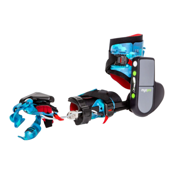
MYOPRO 2+ MOTION G COMPONENTS Reference the diagram below to understand the various components of your MyoPro 2+ Motion G Orthosis. MYOPRO 2+ HAND AND WRIST COMPONENTS Reference the diagram below to understand the various hand and wrist components of your MyoPro 2+ Motion G Orthosis. PN 28010 Rev 001 7 ... -
Page 8: Myopro 2+ Closure Components
MYOPRO 2+ CLOSURE COMPONENTS Reference the diagram below to understand the various components related to the MyoPro 2+ closures of the forearm and humeral straps. MYOPRO 2+ MOTION G FOREARM SENSORS Reference the diagram below to understand the various components related to the MyoPro 2+ forearm sensors. PN 28010 Rev 001 8 ... -
Page 9: Myopro 2+ Biceps & Triceps Sensors
MYOPRO 2+ BICEPS & TRICEPS SENSORS Reference the diagram below to understand the various components related to the MyoPro 2+ biceps & triceps sensors. MYOPRO 2+ CROSS‐BODY HARNESS COMPONENTS Reference the diagram below to understand the various components related to the MyoPro 2+ cross‐body harness. NOTE: Your Provider may have provided you with a harness which differs from the cross‐bosy harness ... -
Page 10: Myopro 2+ Figure 8 Harness Components
MYOPRO 2+ FIGURE 8 HARNESS COMPONENTS Reference the diagram below to understand the various components related to the MyoPro 2+ figure 8 harness. NOTE: Your Provider may have provided you with a harness which differs from the figure 8 harness shown below. If you received a cross‐body harness with your MyoPro 2+, refer to cross‐body harness components diagram on page 9. PN 28010 Rev 001 10 ... -
Page 11: Myopro 2+ Thumb Options
MYOPRO 2+ THUMB OPTIONS Reference the diagram below to understand the two thumb options: Classic and Extended. NOTE: Your Provider will fit you with one of the two thumb types. Please consult with your Provider before switching the thumb. PN 28010 Rev 001 11 ... - Page 12 THIS PAGE IS INTENTIONALLY LEFT BLANK PN 28010 Rev 001 12 ...
-
Page 13: Putting Myopro 2+ Motion Gon ("Donning")
PUTTING MYOPRO 2+ MOTION G ON (“DONNING”) PN 28010 Rev 001 13 ... - Page 14 THIS PAGE IS INTENTIONALLY LEFT BLANK PN 28010 Rev 001 14 ...
-
Page 15: Warnings Review
WARNING: Do not sleep while wearing the MyoPro 2+ as straps may alter the U ser’s circulation. ▲ CAUTION: If you detect fumes, flames, melting of components around the battery or battery charger, or the device is hot to touch, TURN THE DEVICE OFF IMMEDIATELY and contact your Provider. STEPS FOR PUTTING ON MYOPRO 2+ ORTHOSIS To ensure proper fit and function, it is essential the MyoPro 2+ is donned (put on) correctly before each use. If the MyoPro 2+ is donned incorrectly, you may experience discomfort, soreness, and/or pain. You may need assistance to don your MyoPro 2+ and if so, whoever assists you should receive training for proper MyoPro 2+ donning. Myomo offers donning instructional videos for the MyoPro 2+ on its website (www.myomo.com). If you still have difficulty donning the MyoPro 2+, consult with your Provider and/or therapist for tips and strategies specific to your situation. Consult the illustrations above to reference the individual components of the MyoPro 2+, which are identified as italicized words in the following instructions. PN 28010 Rev 001 15 ... -
Page 16: Donning Preparation
Green Arrows indicate motion DONNING PREPARATION Before donning your MyoPro 2+, perform the following steps: 1. Ensure that the MyoPro 2+ is powered off. NOTE: Pads and straps should be fully air‐dried from the previous use. ▲ CAUTION: Do not use a hairdryer to dry components of the MyoPro 2+. 1) Powered‐off MyoPro 2. Remove the finger saddle from the anvil. Simultaneously depress the spring‐loaded finger saddle latch and remove the finger saddle from the anvil. First removing the finger saddle makes the donning process easier. The finger saddle will be re‐attached later. ... - Page 17 3. Loosen the hand strap by removing the hand strap hook from the hand strap anchor by pulling on the red release tab. 3 Unfasten the hand strap 4. Rotate the hand motor out of the way. Simultaneously depress the tilt lever to unlock and lift/rotate the hand motor toward the thumb side so it rotates into the open position. 3 Rotate the hand motor PN 28010 Rev 001 17 ...
- Page 18 5. Position the wrist flexion/extension joint in a neutral position (in‐line with the rest of the brace). Unlock the joint by depressing the flexion/extension button (the black side of button). Lock the wrist flexion/extension joint after positioning in a neutral position. 4 Lock the wrist at neutral 6. Position the wrist supination/pronation joint so the thumb support points down. The wrist/hand should be in the same horizontal position as if you were holding a bike’s handlebars. Unlock the joint by pulling the supination/pronation latch. Position the wrist in line with the forearm bar. Secure the supination/pronation latch after positioning to lock the wrist joint. 6 Rotate the wrist/hand PN 28010 Rev 001 18 ...
- Page 19 7. Completely loosen the forearm magnetic latch and the humeral magnetic latch by pulling on the red release tabs. Open the humeral and forearm shells with the respective straps positioned out of the way . 5 Open the forearm and humeral shells PN 28010 Rev 001 19 ...
-
Page 20: Donning Instructions
DONNING INSTRUCTIONS Prep: If you have tone/spasticity in your hand/fingers, it may be beneficial to employ various techniques to relax your wrist flexors/extensor muscles before proceeding with donning. Consult your therapist/physician for tone/spasticity management solutions. 1. When donning, position the MyoPro 2+ on a surface with adequate friction to prevent it moving away from you, such as your lap. 2. Begin by rotating the hand shell so the fingers are pointing away from you. This will prevent twisting while trying to don the hand piece, which may stimulate tone . NOTE: The motor and battery case should rest on the outside of the arm. If the motor and ... - Page 21 6. If your hand is tight, you will have to uncurl your fingers to pull the hand sufficiently into the hand shell. 7. Position your hand so the base of the thumb is in full contact with the hand shell. Everything is aligned in comparison to the thumb being fully seated against the hand shell. The majority of fit issues occur here. 6 Uncurling the fingers over the hand shell 7 Pull the hand so the knuckles are past the plastic, the thumb web space is in contact 8. Secure the hand strap hook to the hand strap anchor. The hand should be locked in place and unable to remove without releasing the hand strap anchor. If the hand can slip out, tighten the palmar hand strap and/or dorsal hand strap as necessary. 7 Connect the hand strap hook and anchor. Tighten the straps for a very secure fit. ⚠ FIT CHECK ⚠ CONFIRM THE HAND SHELL PLASTIC IS AGAINST THE THUMB WEB SPACE AND THAT THE ...
- Page 22 9. Rotate the hand motor back to the position over the back of the hand by depressing the tilt lever and simultaneously rotating the hand motor back to the closed position. The tilt lever will toggle when the motor assumes the correct position. ...
- Page 23 11.a Rest the forearm into the open forearm shell 11.b Secure Velcro lining, magnetic strapping, and then the clasp 12. Secure the humeral shell. Reach under the armpit to grab and then close the Velcro lining with light tension, ensuring the EMG sensors are not covered by the liner. Secure and attach the humeral magnetic latch to the humeral buckle base. Lock the humeral buckle clasp. 12 Close the humeral shell lining, shell, and then magnetic clasp PN 28010 Rev 001 23 ...
- Page 24 The MyoPro 2+ is now applied. For instructions on donning the harness, please reference the next pages’ instructions to determine which harness you are using and the instructions for application. ...
-
Page 25: Steps For Putting On Myopro 2+ Harness
STEPS FOR PUTTING ON MYOPRO 2+ HARNESS A harness is provided with the MyoPro 2+. It serves to both protect your shoulder joint and to suspend the MyoPro 2+ in correct position on your arm, so it does not slide off. WARNING: A harness should always be worn when the MyoPro 2+ is donned, unless directed otherwise by your physician and/or therapist. Failure to wear a harness may result in shoulder joint discomfort, pain, and/or injury. The MyoPro 2+ is available with two harness models depicted below. Following the appropriate instructions, depending on which harness model you have. CROSS‐BODY HARNESS FIGURE 8 HARNESS ... -
Page 26: Cross-Body Harness Donning
CROSS‐BODY HARNESS DONNING If your MyoPro 2+ was provided with a figure 8 harness, skip this section and proceed to the figure 8 harness donning instructions in the next section. For donning the cross‐body harness, follow the steps below: 1. Place the harness saddle on your shoulder. The suspension straps should straddle your shoulder. The middle of the saddle should be at the midline of the shoulder, touching neither the neck or shoulder joint. ... - Page 27 3. Secure the cross‐body strap using the release tab. The saddle should lay flat against your body. Adjust the angle of the fastened release tab to make the saddle sit evenly and comfortably. There should be slack in the finger adjust loop at this point. 4. Abduct the shoulder with the MyoPro 2+ (lifting it to the side), or use furniture to help lift while pulling the finger adjust loop to tension. When your arm returns to your torso, you should feel the tension of the harness ...
-
Page 28: Cross Body Harness Doffing
CROSS BODY HARNESS DOFFING: When doffing the Cross Body Harness, remove the cross body strap by pulling the release tab from the front . portion of the shoulder saddle Note: Do not remove the harness clips from the MyoPro unless you are removing for laundering purposes. PN 28010 Rev 001 28 ... - Page 29 FIGURE 8 HARNESS DONNING If your MyoPro 2+ was provided with a cross‐body harness, skip this section and refer to the cross‐body harness donning instructions in the preceding section. For donning the figure 8 harness, following the steps below: Orient the harness and check for twists in the strapping. The puck has a surface covered in red fabric, while the other surface is an intersection of the strapping. The red surface of the puck indicates the side that will lay against your back once the harness is donned, while the straps face away from you. Method 1 (flexibility‐dependent) Place the intact‐side arm through the sound side loop with the fabric of the puck facing you. With your arm against the saddle, lift the harness over and behind your head. Gravity will do most of the work as you let it slide down towards your shoulder. You’re done once it’s nestled in your axilla (armpit). 1.3 Adjust the sound side loop so it rests between the chest and shoulder, protecting the collar bone. It shouldn’t make contact with the neck. The anterior suspension strap coming off the front of the MyoPro may require small adjustments to rest similarly. ...
- Page 30 Method 2 (back‐pack method) 2.1 Starting with the harness behind your back, locate the puck using your sound side. Orient the puck so that the fabric side is towards your back, while the straps face away from the you. This will keep the harness oriented in the correct position as you move your hand into the sound side loop. Take note that both of the harness straps from the MyoPro begin around the back of the device. The anterior suspension strap will be moved into position at the end. 2.2 With the sound side loop around your intact‐side wrist, begin to wriggle the loop up your arm, towards your shoulder. The final motion will require a shoulder shrug to help the strapping cross your shoulders to the front of your body. 2.3 Adjust the sound side loop so it rests between the chest and shoulder, protecting the collar bone. It shouldn’t make contact with the neck. The anterior suspension strap coming off the front of the MyoPro may require small adjustments to rest similarly. ...
- Page 31 FIGURE 8 HARNESS DOFFING Slide the anterior suspension strap off of the MyoPro‐side shoulder. There should then be enough slack to remove the sound side loop off the intact side. Resting your intact arm at your side will allow the sound side loop to fall down your arm. It may take minor maneuvering, but once the loop is past your elbow, simply lifting the sound side arm will finish removing the harness. FIGURE 8 ADJUSTMENT The harness can be made looser by pulling forward The harness can be tightened by pulling back on the sound on the anterior adjustment buckle side loop strap that exits the anterior adjustment buckle ...
-
Page 32: Adjusting Wrist Module
ADJUSTING WRIST MODULE PN 28010 Rev 001 32 ... - Page 33 The wrist module position along the user’s forearm (proximal‐distal) can be adjusted two different ways. 1. Method 1: Move the Hand Carrier Bar in the Flexion/Extension Joint. This can be done by loosening and retightening these set screws with a 3 mm hex key. It is recommended to tighten the set screws to 5 inch/lbs, or approximately a ¼ turn (90 degrees) after making contact. 2. Method 2: Move the wrist module along the forearm bar. This can be done by loosening and retightening this set screw with a 2 mm hex key. It is recommended to tighten the set screw to 5 inch/lbs, or approximately a ¼ turn (90 degrees) after making contact. Method 1 Open the Supination/Pronation (SP) Latch to adjust the pronation and supination of the ADJUST SP Joint. Close the SP Latch once the joint is in the desired location. PN 28010 Rev 001 33 ...
- Page 34 Open Latch Closed Latch Caution: The SP latch should be closed when the device is not in use to avoid accidental damage to the components. Push the Flexion/Extension Button to the unlocked position (shown below) to unlock ADJUST the Hand Carrier Bar, then adjust the Hand Carrier Bar. Push the Flexion/Extension Button to the locked position to lock the Hand Carrier Bar in the desired position. PN 28010 Rev 001 34 ...
- Page 35 Unlocked Locked PN 28010 Rev 001 35 ...
- Page 36 THIS PAGE IS INTENTIONALLY LEFT BLANK PN 28010 Rev 001 36 ...
- Page 37 TAKING OFF MYOPRO 2+ (“DOFFING”) PN 28010 Rev 001 37 ...
- Page 38 THIS PAGE IS INTENTIONALLY LEFT BLANK PN 28010 Rev 001 38 ...
-
Page 39: Steps For Taking Off Myopro 2
WARNINGS REVIEW WARNING: If at any time during the use of this device, you notice any of the following, discontinue use and seek guidance from your Provider. Movement does not match the User’s desired motion. Persistent redness, swelling, or skin breakdown (bleeding, chafing, etc.) Rash on the arm, hand, or fingers. Pain associated with wearing the MyoPro 2+ orthosis. Unusual noises from the orthosis (popping, clicking, etc.) Smells from the orthosis (smoking, burning plastic, etc.) Odor from the orthosis (sour smells or other indications of bio‐contamination.) STEPS FOR TAKING OFF MYOPRO 2+ To remove the MyoPro 2+, referred to as “doffing the MyoPro 2+”, follow the steps below: 1. Ensure that the MyoPro 2+ is turned OFF. 2. Place the MyoPro 2+ in your lap, or on a flat surface that is not slippery. 3. Remove the finger saddle (see page 1 for images). 4. Undo the hand strap hook from the hand strap anchor. 5. Align the multi‐articulating wrist into a neutral position using the flexion/extension joint and supination/pronation ring. 6. Open the forearm cuff. Pull on the forearm red release tab to release the forearm buckle from the forearm buckle base. 7. Open the humeral cuff. Note, once the humeral cuff is loose, the MyoPro 2+ may fall away from your arm. Be sure to secure the MyoPro 2+ first so that it does not fall. Pull on the humeral red release tab to release the humeral buckle from the humeral buckle base. 8. - Page 40 THIS PAGE IS INTENTIONALLY LEFT BLANK PN 28010 Rev 001 40 ...
-
Page 41: Operating Myopro 2
OPERATING MYOPRO 2+ PN 28010 Rev 001 41 ... - Page 42 THIS PAGE IS INTENTIONALLY LEFT BLANK PN 28010 Rev 001 42 ...
- Page 43 CONTROL PANEL See the User Manual – Sections for All MyoPro 2+ Models document for a comprehensive Control Panel Buttons & Lights Diagram. Power Button Mode Buttons PN 28010 Rev 001 43 ...
-
Page 44: Modes Of Use
MODES OF USE WARNING: Use caution when using the device in shoulder positions where it is possible for the User to hit him or herself. The MyoPro 2+ may be used in a variety of modes. The different modes allow you to operate the MyoPro 2+ by tensing or relaxing different muscles. You may find that you want to use different muscles – and therefore different modes – when performing specific tasks with your MyoPro 2+. Modes may be changed using the buttons on the control panel. When the device is fit to you, your Provider will optimize the sensitivity settings within each mode depending on the strength of your EMG signal at that time. If over time you feel that the MyoPro 2+ is not assisting your arm or hand adequately, please contact your Provider; the sensitivity settings may need to be readjusted. START MODE When you first power on the MyoPro 2+, the elbow will be in Standby Mode. This setting may be changed by your Provider. ELBOW MODES The elbow has four distinct modes of use when the MyoPro 2+ is powered on. 1. Standby mode 2. Biceps mode 3. Triceps mode 4. Dual mode These are explained in the following pages. GRASP MODES The grasp has four distinct modes of use when the MyoPro 2+ is powered on. 1. Standby mode 2. Open mode 3. Close mode 4. Dual mode These are explained in the following pages. ... -
Page 45: Elbow Modes
ELBOW MODES In this mode, neither the Biceps or Triceps Light will be illuminated. The elbow motor will not respond to your EMG signal from either muscle group. Though the MyoPro 2+ is powered on, no assistance is being given to your elbow, and the arm will neither flex nor e xtend. The sensors will be reading your EMG signal from both biceps and triceps, but the motor response is paused. Standby mode Actions: • This can be useful as a resting mode if straps or sensors need to be adjusted, or if you want to take a short b reak without turning the device off. In this mode, the Biceps Light will be illuminated. The elbow motor will respond to your biceps EMG signal. ... - Page 46 , ELBOW MODES CONTINUED In this mode, the Triceps Light will be illuminated. The elbow motor will respond to your triceps EMG signal. Actions: • When you relax your triceps, the elbow will flex. • When you contract your triceps, the elbow will extend. Triceps mode In this mode, both the Biceps and Triceps Light will illuminate. The elbow motor will respond to your biceps and triceps EMG signal. The elbow will only respond to muscle contraction (not relaxation, as in other modes) to assist you with active flexion and active extension of your elbow. ...
-
Page 47: Grasp Modes
GRASP MODES In this mode, neither the Close or Open Light will be illuminated. The grasp motor will not respond to your EMG signal. Though the MyoPro 2+ is powered on, no assistance is being given to your hand, and the grasp will neither open nor close. The sensors will be reading your EMG signals from both wrist flexor and extensor muscle groups, but the motor response is paused. Standby mode Actions: • This can be useful as a resting mode if straps or sensors need to be adjusted, or if you want to take a short b reak without turning the device off. In this mode, the Close Light will be illuminated. The grasp motor will respond to your wrist flexor EMG signal. ... - Page 48 , GRASP MODES CONTINUED In this mode, the Open Light will be illuminated. The grasp motor will respond to your wrist extensor EMG signal. Actions: • When you relax your wrist extensors, the grasp will c lose. • When you contract your wrist extensors, the grasp will open. Open mode In this mode, both the Close and Open Light will illuminate. The grasp motor will respond to your wrist flexor and wrist extensor EMG signal. The grasp will only respond to muscle contraction (not ...
-
Page 49: Changing Elbow Mode With The Control Panel
CHANGING ELBOW MODE WITH THE CONTROL PANEL The elbow mode button cycles through the 4 elbow modes, moving to the next mode each time you press the mode button. When the MyoPro 2+ is turned ON, the elbow will be in Standby mode unless it has been changed by your Provider. Press the elbow mode button one time to put the elbow into Biceps mode Press the elbow mode button again (a second time) to put the elbow into Triceps mode Press the elbow mode button again (a third time) to put the elbow in Dual mode Press the elbow mode button again (a fourth time) to return the elbow Standby mode Repeat the above cycle to scroll through and change to another mode at any point during your MyoPro 2+ use. CHANGING GRASP MODE WITH THE CONTROL PANEL The grasp mode button cycles through the 4 grasp modes, moving to the next mode each time you press the mode button. When the MyoPro 2+ is turned ON, the grasp will be in Standby mode unless it has been changed by your Provider. Press the grasp mode button one time to put the grasp into Close mode Press the grasp mode button again (a second time) to put the grasp into Open mode Press the grasp mode button again (a third time) to put the grasp in Dual mode Press the grasp mode button again (a fourth time) to return the grasp Standby mode Repeat the above cycle to scroll through and change to another mode at any point during your MyoPro 2+ use. PN 28010 Rev 001 ...
Need help?
Do you have a question about the myopro 2+ Motion G and is the answer not in the manual?
Questions and answers