Table of Contents
Advertisement
Quick Links
Allegro 18" Integral Conveyor
DORNER MFG. CORP.
P.O. Box 20 • 975 Cottonwood Ave.
Hartland, WI 53029-0020 USA
851-824 Rev. A
Maintenance & Parts Manual
For other service manuals visit our website at:
www.dorner.com/service_manuals.asp
INSIDE THE USA
TEL: 1-800-397-8664
FAX: 1-800-369-2440
OUTSIDE THE USA
TEL: 262-367-7600
FAX: 262-367-5827
Advertisement
Table of Contents

Subscribe to Our Youtube Channel
Related Manuals for Dorner Allegro 18"


Summary of Contents for Dorner Allegro 18"
- Page 1 Allegro 18" Integral Conveyor Maintenance & Parts Manual DORNER MFG. CORP. INSIDE THE USA OUTSIDE THE USA P.O. Box 20 • 975 Cottonwood Ave. TEL: 1-800-397-8664 TEL: 262-367-7600 Hartland, WI 53029-0020 USA FAX: 1-800-369-2440 FAX: 262-367-5827 For other service manuals visit our website at: www.dorner.com/service_manuals.asp...
-
Page 2: Table Of Contents
• Compare shipment with packing slip. Contact factory regarding discrepancies. • Inspect packages for shipping damage. Contact carrier regarding damage. • Accessories may be shipped loose. See accessory instruc- tions for installation. Dorner’s Limited Warranty applies. Allegro 18" Integral Conveyor Dorner Mfg. Corp. 851-824 Rev. A... -
Page 3: Warnings − General Safety
A WARNING The safety alert symbol, black triangle with white exclamation, is used to alert you to potential personal injury hazards. Dorner cannot control the physical A DANGER installation and application of conveyors. Taking protective measures is the responsibility of the user. -
Page 4: Product Description
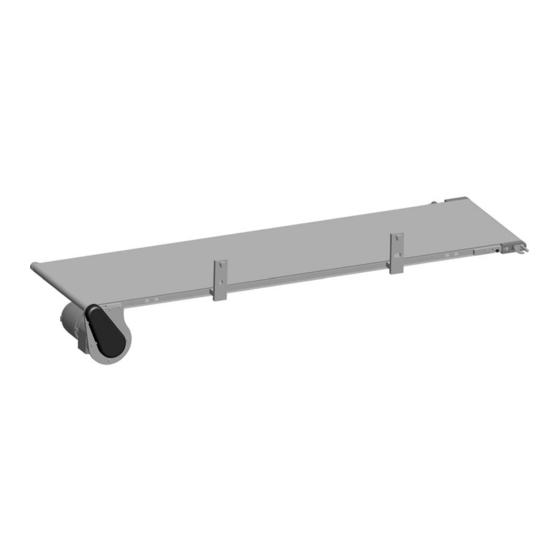
Product Description Refer to Figure 1 for typical components. Drive End Gearmotor Mounting Package Idler/Tension End Conveyor Mounting Brackets Figure 1 Figure 1 Allegro 18" Integral Conveyor Dorner Mfg. Corp. 851-824 Rev. A... -
Page 5: Preventive Maintenance And Adjustment
During first installation, make sure that the M5 screws are backed out equally on each side. Figure 4 Figure 4 Tighten the M6 screws (Figure 4, item 2) on both sides of the conveyor. Allegro 18" Integral Conveyor 851-824 Rev. A Dorner Mfg. Corp. -
Page 6: Idler Pulley Removal
Slide the spindle out. To replace the idler tail pulley, reverse the removal Figure 5 procedure. Install belt on the conveyor, then tension the belt. See “Conveyor Belt Tensioning/Tracking” on page Allegro 18" Integral Conveyor Dorner Mfg. Corp. 851-824 Rev. A... -
Page 7: Drive Pulley Removal
To prevent damage to the head plates, be sure to remove them slowly because they are not attached to pulley. Figure 11 Figure 9 Figure 11 Slide the spindle out. Allegro 18" Integral Conveyor 851-824 Rev. A Dorner Mfg. Corp. -
Page 8: Bearing Removal & Replacement
Using puller part #807−1716 (Figure 13, item 1), Slide sleeve (Figure 16, item 1) of tool (part #456085) remove and discard bearing. over bearing. Figure 13 Figure 16 Figure 16 Figure 13 Allegro 18" Integral Conveyor Dorner Mfg. Corp. 851-824 Rev. A... -
Page 9: Gearmotor Mounting Package Removal
Drive shaft keyway may be sharp. HANDLE Replacement” on page WITH CARE. Loosen set screw (Figure 20, item 3) on driven pulley (Figure 20, item 4). Remove driven pulley and timing belt. Allegro 18" Integral Conveyor 851-824 Rev. A Dorner Mfg. Corp. - Page 10 Remove eight screws (Figure 25, item 1). Remove gearmotor (Figure 25, item 2) and mount plates Figure 22 (Figure 25, item 3) from motor mount plate (Figure 25, item 4). Figure 25 Figure 25 Allegro 18" Integral Conveyor Dorner Mfg. Corp. 851-824 Rev. A...
-
Page 11: Timing Belt Tensioning
Removal” on page 9. Replace drive or driven pulley. Tighten set screws. Complete steps 2-4 of “Timing Belt Replacement” on page 11. Figure 27 Install timing belt covers and tighten four screws. Allegro 18" Integral Conveyor 851-824 Rev. A Dorner Mfg. Corp. -
Page 12: Gearmotor Replacement
For single phase motor, unplug power cord from outlet. For variable speed motor, unplug cord at disconnect (Figure 28, item 1). Figure 28 Figure 28 Replace gearmotor. See “Gearmotor Mounting Package Removal” on page Allegro 18" Integral Conveyor Dorner Mfg. Corp. 851-824 Rev. A... -
Page 13: Notes
Notes Allegro 18" Integral Conveyor 851-824 Rev. A Dorner Mfg. Corp. -
Page 14: Service Parts
Service Parts NOTE For replacement parts other than those shown in this section, contact an authorized Dorner Service Center or the factory. Key Service Parts and Kits are identified by the Performance Parts Kits logo . Dorner recommends keeping these parts on hand. - Page 15 M6-1.00 x 16 mm 960625MSS Hex Head Cap Screw, M6-1.00 x 25 mm 960645MSS Hex Head Cap Screw, M6-1.00 x 45 mm 960816MSS Hex Head Cap Screw, M8-1.25 x 16 mm Allegro 18" Integral Conveyor 851-824 Rev. A Dorner Mfg. Corp.
-
Page 16: Frame Assembly
Service Parts Frame Assembly Allegro 18" Integral Conveyor Dorner Mfg. Corp. 851-824 Rev. A... - Page 17 M6-1.00 x 20 mm 960625MSS Hex Head Cap Screw, M6-1.00 x 25 mm 960630MSS Hex Head Cap Screw, M6-1.00 x 30 mm 960640MSS Hex Head Cap Screw, M6-1.00 x 40 mm Allegro 18" Integral Conveyor 851-824 Rev. A Dorner Mfg. Corp.
-
Page 18: Return Policy
RMA will automatically close 30 days after being issued. To get credit, items must be new and undamaged. There will be a return charge on all items returned for credit, where Dorner was not at fault. It is the customer’s responsibility to prevent damage during return shipping.
Need help?
Do you have a question about the Allegro 18" and is the answer not in the manual?
Questions and answers