Table of Contents
Advertisement
Quick Links
Advertisement
Table of Contents

Subscribe to Our Youtube Channel
Related Manuals for Carrier Airovision 39HQ


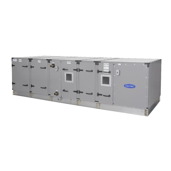
Summary of Contents for Carrier Airovision 39HQ
- Page 1 39HQ Airovision Air Handling Units Mounting instructions...
-
Page 2: Table Of Contents
CONTENTS 1 - TRANSPORT AND LIFTING INSTRUCTIONS ........................3 1.1 - General ......................................3 1.2 - Transport and storage .................................. 3 1.3 - Roof edge protection during transport (outside installation) ...................... 3 1.4 - Offl oading and hoisting ................................3 1.5 - Horizontal transport .................................. -
Page 3: Transport And Lifting Instructions
Transport and lifting must be carried out by qualifi ed personnel. These points are marked by the label shown below. The AHU must only be lifted with lifting bars supplied by Carrier Holland Heating. Lifting must be carried out in accordance Fig. -
Page 4: Horizontal Transport
• Connecting strips/screws • Lifting bars • Slide the lifting bar into the hole in the subframe intended for that purpose. The following material is supplied as an option by Carrier Holland Heating: • Siphon • Anti-vibration mats • Outside air suction grille... -
Page 5: Assembly
AHU section has not yet been placed. Ensure that the bolt and Fig. 8 - Fastening the lifting bars - 2 the locking plate are removed from the right-hand side of the lifting bar, when the 6th AHU section has been positioned. Fig. -
Page 6: Connecting Casings Of Equal Width And Height
Method 1 4.2 - Connecting casings of equal width and height Pull the sections against each other, using the pull ropes attached Fig. 15 - Unit of equal width and length to the lifting bars. Pull evenly on both sides of the AHU. Fig. -
Page 7: Connecting Casings Of Differing Height
Fig. 18 - Corner connection Fig. 21 - Fixing sealing tape to the corner posts • Link the sections by connecting the pre-mounted corner posts with bolts and nuts (M6). Fig. 22 - Connecting the corner posts • Remove the fi rst two corners and mount the aluminium connection strip to the base. -
Page 8: Stacked Casing Sections
Method 1 5. STACKED CASING SECTIONS • Check if the cover strip has been applied at the correct height on the projecting section. 5.1 - Unit without intermediate base frame (equal width) • Fix the plastic fi nish layer to cover strip above with the screws provided. -
Page 9: Unit With Intermediate Base Frame (Equal Width)
• A longer top section needs no further fi nish at the ends. Fig. 28 - Mounting profi le, outdoor location, unit without intermediate base frame Fig. 31 - Unit with longer top section without intermediate base frame NOTE: For outdoor installation seal all jonts resulting from the mounted profi les. - Page 10 Fig. 34 - Fixing profi le, indoor location with Fig. 36 - Fixing profi le, length direction, unit with intermediate base frame intermediate base frame Cross section of length direction (A-A) There is no need for a connection profi le at the ends of the unit. •...
-
Page 11: Units With Differing Widths
• If the top section is shorter than the bottom section, the 5.3 - Units with different widths unit ends should be fi nished as described below. For units with different widths there are four different situations. Fig. 38 - Unit with shorter top section with For an indoor installation the method described below applies intermediate base frame to all situations. - Page 12 Fig. 43 - Unit of unequal width - situation A Fig. 46 - Unit of unequal width - situation C • Side 1: Cut the connection profi le to the correct length and • Side 1: Cut the connection profi le to the correct length and mount it on the correct side (see Fig.
-
Page 13: Fresh Air Inlet Hood
• Side 1 and 2: Cut the connection profi les to the correct Fig. 51 - Roof fi nish. method 1 length and mount them on the correct side (see Fig. 44) • Side 3: Cut the connection profi le to the correct length and mount it on the correct side (see Fig. - Page 16 Fax: +31 (0) 416 37 17 95 www.carrier.nl Order No.: 13951-06, 09.2006. Supersedes order No.: New. Manufactured by: Carrier Holland Heating, Waalwijk, Netherlands Manufacturer reserves the right to change any product specifi cations without notice. Printed in the Netherlands on chlorine-free paper.
Need help?
Do you have a question about the Airovision 39HQ and is the answer not in the manual?
Questions and answers