Advertisement
Quick Links
Advertisement

Related Manuals for Broyhill BL-TV-060-21A


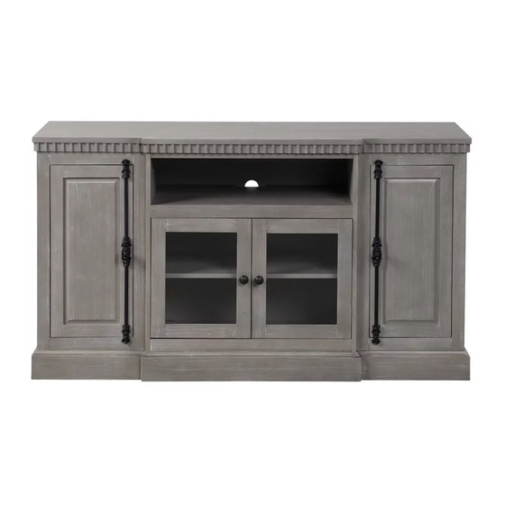
Summary of Contents for Broyhill BL-TV-060-21A
-
Page 2: Maintenance
GENERAL BEST PRACTICES FOR ASSEMBLY: Determine you have adequate space for assembly. Assembly by two adults is recommended. Assemble on soft surfaces to prevent damage to product finish. Keep children away during assembly. This item contains small parts which can be swallowed by children. -
Page 3: Parts List
PARTS LIST Top Panel Left Side Panel Left Middle Panel x 1 pc x 1 pc x 1 pc Right Middle Panel Right Side Panel Left Door x 1 pc x 1 pc x 1 pc Right Door Middle Door Center Crossbar x 1 pc x 2 pcs... - Page 4 PARTS LIST Side Back Panel Center Back Panel Center Middle Panel x 2 pcs x 1 pc x 1 pc Center Adjustable Shelf Adjustable shelves Bottom Crossbar x 1 pc x 2 pcs x 1 pc Bottom Panel Back Crossbar Connect Wood x 1 pc x 1 pc...
-
Page 5: Hardware List
HARDWARE LIST Allen Key x 1 pc Flat Washer x 60 pcs Allen Bolt x 56 pcs Spring Washer x 56 pcs Ø1/4" Ø1/4"*32mm Ø1/4" Hinge x 4 pcs Wood Dowel x 28 pcs Screw x 8 pcs Plastic Block x 8 pcs Ø8*30mmL Ø7*19mmL 30*14*8mm... - Page 6 STEP 1 Hardware needed With assistance, place the Bottom Panel (P) upside down on a smooth surface. Attach the Back Crossbar (Q) to Bottom Panel (P) with Flat Washer (3), Spring Washer (2) and Allen Bolt (1) using Allen Key (4). Fully tighten all bolts.
- Page 7 STEP 2 Hardware needed Place the Left Side Panel (B) upside down on a smooth surface. Align the holes in Connect Wood (R) with the holes in Left Side Panel (B) as shown. Secure Connect Wood (R) to Left Side Panel (B) with Flat Washer (3), Spring Washer (2) and Allen Bolt (1) using Allen Key (4).
- Page 8 STEP 3 Hardware needed Insert Wood Dowel (5) into Left Middle Panel (C). Align the holes in Center Crossbar (I), Center Middle Panel (L) and Bottom Crossbar (O) and slide to place. Repeat process to attach the Center Crossbar (I), Center Middle Panel (L) and Bottom Crossbar (O) to Right Middle Panel (D).
- Page 9 STEP 4 Hardware needed Insert Wood Dowel (5) into holes of Bottom Panel (P). With assistance, align the holes in Left Middle Panel (C) and Right Middle Panel (D) with inserted Wood Dowel (5) and lower to place. Secure the Bottom Crossbar (O), Left Middle Panel (C), Right Middle Panel (D) to Bottom Panel (P) with Flat Washer (3), Spring Washer (2) and Allen Bolt (1) using Allen Key (4).
- Page 10 STEP 5 Hardware needed With assistance, align the hole in connect wood assembled on Left Door (F) with the holes in Left Middle Panel (C), Bottom Panel (P) and slide into place. Attach Left Door (F) to Left Middle Panel (C) and Bottom Panel (P) with Flat Washer (3), Spring Washer (2) and Allen Bolt (1) using Allen Key (4).
- Page 11 STEP 6 Hardware needed Insert Wood Dowel (5) into holes of Bottom Panel (P). With assistance, align the holes in Left Side Panel (B) with inserted wood dowels and lower to place. Attach the Left Side Panel (B) to Bottom Panel (P) and Left Door (F) with Flat Washer (3), Spring Washer (2) and Allen Bolt (1) using Allen Key (4).
- Page 12 STEP 7 Hardware needed Open Center Back Panel (K). Insert Center Back Panel (K) down along the groove of Left Middle Panel (C) and Right Middle Panel (D). Insert Side Back Panel (J) down along the groove of Left Side Panel (B) and Left Middle Panel (C). Repeat the process for the remain Side Back Panel (J) to attach to Right Side Panel (E) and Right Middle Panel (D).
- Page 13 STEP 8 Hardware needed Insert the Shelf Pin (12) into the pre-drilled holes as shown in the diagram. Place Adjustable Shelf (N) onto the Shelf Pins as shown. Repeat the process for the remaining Adjustable Shelf (N) and the Center Adjustable Shelf (M). You can adjust the position of shelf as needed.
- Page 14 STEP 9 Hardware needed Place the Plastic Block (6) into the corner of Side Back Panel (J) as shown. Insert Screw (7) into the pre-drilled holes and secure with Phillips Screwdriver. Fully tighten screws. Repeat the step for the remaining Plastic Block. Insure all Plastic blocks are used to secure both side back panels in place.
- Page 15 STEP 10 Hardware needed Attach the Anti-tipping Strips (15) to the back top of the mantel with Screw (17) and Flat Washer (3). With assistance, place the console in the desired location and mark the wall just below the spot where the Aniti-tipping Strips are attached to the console. Remove the console.
- Page 16 WARNING The maximum diagonal Plasma/LCD television screen size is 60inch (152.40cm). For use with televisions weighing 135 lbs. (61.23 kg) or less. Using larger or heavier televisions may cause instability or tip-over which lead to serious injury or even death. WARNING - Death or serious injury may occur when children climb on audio and/or video equipment furniture.
- Page 17 ASSEMBLY IS COMPLETED PRINTED IN VIETNAM Page 16 of 16...
Need help?
Do you have a question about the BL-TV-060-21A and is the answer not in the manual?
Questions and answers