
Subscribe to Our Youtube Channel
Related Manuals for Heraeus Ut 6 P

Summary of Contents for Heraeus Ut 6 P
-
Page 1: Added-Feature Programming Functions, Example 2 0 - 2
(GET) INSTRUCTION MANUAL INSTRUMENTS Laboratory Air Circulation Ovens Models UT 6 P, UT 12 P, UT 20 P Comply with the operating instructions and keep this manual in the vicinity of the unit I Issue: May, 1994 50 042 750... - Page 2 ++ (0 61 81) 3 5 - 6 67 O Heraeus Instruments GmbH. 63450 Hanau, Germany function line* is a registered trademark of Heraeus Instruments GmbH The German version of this Instruction manual applies in the event of any deviations in the translation...
-
Page 3: Table Of Contents
CONTENTS 1. GENERAL SAFETY INSTRUCTIONS 4 - 6 Explanation of icons General information Operating instructions Field of application Safely instructions 2. SETUP AND INSTALLATION 7 - 9 Transport Unpacking the unit Installation Room ventilation Mains connection Noise insulation Connecting to an air extraction system 3. -
Page 4: General Safety Instructions
GENERAL SAFETY INSTRUCTIONS EXPLANATION OF ICONS This symbol marks chapters and sections of this instruction manual which are particularly relevant lo safety. When attached to the unit, this symbol draws attention to the relevant section of the instruction manual. Marks information about optimum utilization of the unit in the instruction manual. Warns of hot surfaces. -
Page 5: General Information
GENERAL SAFETY INSTRUCTIONS General information The unit fulfils the following safety standards: DIN EN 61 0 1 0 - 1 / 0 3 . 9 4 . VDE 0411 Part 1 / 0 3 / 9 4 , E D I N V D E 0411 Part 111. DIN 12 880 Part 1 / 1 1 . -
Page 6: Safely Instructions
Heraeus Instruments GmbH cannot accept any liability for any damage that occurs as a result or improper use or repair work, which has not been performed by Heraeus service centers, or if parts other than the approved genuine spare parts / accessories are used. -
Page 7: Setup And Installation
*m>JI If the unit UT 6 P is to be fitted under a table or into a laboratory fixture, it must be connected to an exhaust air extraction system. The top clearance may only be reduced to min. 5 cm under such circumstances. -
Page 8: Room Ventilation
SETUP AND INSTALLATION Room ventilation Adequate ventilation must be provided wherever the unit is installed. Do not operate the unit In non-ventilated enclosed spaces. Special ventilation measures (e.g. ventilation of designated work areas, FRG also refer to VDI 1946 Part 7) when several units are Installed in one room. Mains connection The laboratory unit is supplied with a permanently connected, flexible mains power lead with connector (grounded). -
Page 9: Connecting To An Air Extraction System
SETUP AND INSTALLATION Connecting to an extraction system Comply with the applicable national environmental regulations for the extraction of exhaust gases released during the heat treatment. Suitable measures must be implemented to ensure that such gases are safely led outside (FRG: BlmSchG). Such measures may involve thermal or catalytic treatment of flue gases. -
Page 10: Unit Specification
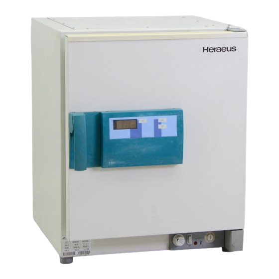
UNIT SPECIFICATION Fig. 1/3: Overview of the control elements Switchgear unit Automatic control unit Door handle — i—. Item A: Swltchgear unit 2/3: Switchgear unit control panel Fig. On / Off switch Overtemperature protection, control element "Fault" signal lamp Fresh-air flap adjustment •... -
Page 11: Overtemperature Protection Device
UNIT SPECIFICATION • 2 & 3 Overtemperature protection device / signal lamp: Functional test of the TWB (Prerequisite: required working temperature (control unit) has been reached /remains constant) Set the TWB to approx. 10 - 20 'C below the temperature displayed on the control unit. The TWB must respond, the red signal lamp indicates "Fault". -
Page 12: Automatic Control Unit
UNIT SPECIFICATION Item B: Automatic control unit The automatic control unit contains the basic functions of a 2-posilion controller with PD/PID control response, time switch to switch the heating and ventilation on / off after the set time, the added features of permanently programmed heating process programs and the programmed controller functions of a freely programmable process controller. -
Page 13: Added-Feature Programming Functions, Fixed Programs
UNIT SPECIFICATION Added-feature programming functions, fixed programs The control unit is capable of running heating process programs with fixed, preselected parameters from a database. The program segment and the parameters are stored in the database. The fixed program contains a maximum of four program segments and a status command. Fig. -
Page 14: Fixed Program Segments
• Fixed program segments: Program segment" P 1. n " (n = -, 0... 9): Assigning a parameter (0 ... 9) from the database causes the unit to switch on heating and ventilation on expiry of a preset period. Selectable parameters In this program segment: PI. -
Page 15: Example Of A Fixed Program
UNIT SPECIFICATION • Example of a fixed program *• Example E1: Hot-air sterilization process The heating should switch on in 8 hours, the unit should heat up to an operating temperature of 190 *C (sterilization temperature) at a rate of 200 *C/h, maintain this temperature for 4 hours (equalization phase and sterilization period) and should subsequently cool down at a rate of 20 •C/h. -
Page 16: Programmed Controller Function
OPERATION Programmed controller function The programmed controller function enables the arbitrary definition of temperature / time processes. You may select up to 9 program segments. Operating temperature, period and air speed level can be selected for each segment. Termination commands A termination command can be selected as the last program segment. -
Page 17: What Happens If
OPERATION What happens if ... ? Possible display Explanation 8 8 8 Control unit test phase O F F Status of the control unit, heating and ventilation disabled One digit in the display flashes The flashing value can be changed P1.3 Program segment when entering an added-feature program function P 1.3 alternating with inside... -
Page 18: Operation
OPERATION Afler letup and Installation, proceed as follows to start up: Starting up with basic functions, without programming Key(s) Example ol display Remarks Instruction The green status display On / Off switch = "on" Switch unit on indicates the status. Display panel: inside temperature The unit runs through a self-test phase after switching on, display: "... - Page 19 OPERATION Setting the switching time Remarks Key(s) Example of display Instruction Display flashes, lime-swilch Select time-switch I I II I funcition is displayed. If liming function, display time I.I II I period in progress, displays remaining for timing time remaining period Increase preset time Value can be adjusted...
- Page 20 OPERATION Fig. 1/4: Example of a hot-air sterilization process S 1 - S 4 • Programmsegment 190 *C P 3 . 5 P.onl The heating is to switch on in 8 hours, the unit should heat up to 190 'C at 200 'C/h, maintain this temperature for 4 hours, then switch off.
- Page 21 OPERATION Entering the status command Instruction Key(s) Example of display Remarks P. o n is displayed, mark with Select and mark status command P. o n the "set" key Leave the program Display alternates between memory inside temperature and " P r o " Input terminated Starting the added-feature program Start the program...
- Page 22 UKtKMIION Fig. 2/4: Example of the programmed controller function with " StOP " termination command 100% / vV I n 10 = StOP The program sequence from a total of 9 segments must be entered, after which the healing and ventilation is to be switched off.
- Page 23 OPERATION Entering the temperature for a program segment Instruction Key (s) Example of display Remarks Enter operating Preset operating temperature T 1, temperature for 230 *C program segment 1(n I) Mashes in display If" —" appears In the display when the set key is pressed, then "hold" or "StOP" has been enlered as the termination command for program segment n I.
- Page 24 OPERATION Entering the air speed level for a program segment nstruclion Key(s) Example of display Remarks Select Ihe preset air Air speed level flashes speed level lor in the display, speed program segment n I symbol Select air speed level, approx.
- Page 25 OPERATION Leaving the program memory Input terminated Starting the program Instruction Key (s) Example of display Remarks | approx. 6 sec. Inside temperature Start the program II I I I and program segment are displayed Terminating the program Instruction Key(s) Example of display Remarks Terminate the program...
- Page 26 OPERATION Fig. 3/4: Example of the programmed controller function with " hold " termination command 100% nA 'hold •4 •4 Starting up with programmed controller function The "hold" termination command has been selected here as an alternative to example 2/4. Enter the preset temperature, time and air speed level values for the program segments according to the same procedure as example 2/4.
- Page 27 OPERATION Fig. 3/4: Example of the programmed controller function with " CYCL " lerminalion command 100% 4 0 % 40 % ^ » < " • n 5 • CYCL Starting up with the programmed controller function The "CYCL" termination command has been selected here as an alternative to example 274. Enter the preset temperature, time and air speed level values for the program segments according to the same procedure as example 2/4.
-
Page 28: Operating Guidelines
UfCKAIlUN Operating guidelines Remember to put on protective garments, e.g. gloves, goggles, mask, body protection, remove any items of jewellery before starting work. Do not cover or obstruct the ventilation or exhaust vents in the unit housing. Always keep these vents free of dust and dirt •... -
Page 29: Maintenance
Heraeus Instruments GmbH cannot accept any liability for any damage that occurs as a result of improper use or repair work, which has not been performed by Heraeus service centers, or if parts other than the approved genuine spare parts / accessories are used. -
Page 30: Servicing
Only approved genuine spare parts and accessories may be used. The use of other parts may result in unforeseen problems and should be avoided under all circumstances. Approved spare parts /accessories Spare part /accessory Heraeus order number Size / model U T 6 P UT20P UT12P... - Page 31 TECHNICAL DATA Unit U T 2 0 P U T 6 P U T 1 2 P DATA Model $Wffl^^&$mSS^S.^ *• • • : ••.;• 696 x 850 x 685 7 5 4 x 9 1 0 x 8 6 5 Housing 552 x 700 X 685 Dimensions...
-
Page 32: Technical Data
TECHNICAL DATA DATA Model U T 6 P Unit UT12P UT20P THERMAL Warm-up-timos, (resh-air mode (unit empty, air (lap open, to 98 % of the operating temperature) Operating 70 'C temperature 250'C Cool-down times, circulating mode (unit empty, air flap closed, to 50 *C) Operating 250 *C temperature... - Page 33 TECHNICAL DATA UT20P [Unit U T 6 P U T 1 2 P Model DATA ELECTRICAL (rated values) 1/PEAC. 230 Rated voltage Rated frequency 5 0 / 6 0 Power consumption 1.27 2.32 2 32 Connected load Current input 10.1 10.1 Protection class Protective measure...
- Page 34 TECHNICAL DATA © Component Materials used Outer casing Galvanized sheet steel, painted RAL 9002 Heat sink (rear panel) Aluminium Inner chamber Stainless steel, material No. 1.4301 Components litted in the chamber Stainless steel, material No. 1.4301 Trays Chromium-plated steel wire Door seal Seasoned silicone rubber PA, glass fiber reinforced...
Need help?
Do you have a question about the Ut 6 P and is the answer not in the manual?
Questions and answers
Does it need Calibration every year?
The manual states that certain items should be tested at least once a year to ensure the unit remains in good working order. These include mechanical functions, operation according to technical data, the electrical system, and safety devices. However, it does not explicitly mention "calibration." Therefore, while annual testing is required, the need for calibration is not specifically stated.
This answer is automatically generated