Juniper SSG 140 Hardware Installation And Configuration Manual
Hide thumbs
Also See for SSG 140:
- Product overview (7 pages) ,
- Hardware installation and configuration manual (62 pages) ,
- Manual (20 pages)

Related Manuals for Juniper SSG 140


Summary of Contents for Juniper SSG 140
- Page 1 Security Products SSG 140 Hardware Installation and Configuration Guide Juniper Networks, Inc. 1194 North Mathilda Avenue Sunnyvale, CA 94089 408-745-2000 www.juniper.net Part Number: 530-015643-01 Revision 05...
- Page 2 Networks or their respective owners. All specifications are subject to change without notice. Juniper Networks assumes no responsibility for any inaccuracies in this document or for any obligation to update information in this document. Juniper Networks reserves the right to change, modify, transfer, or otherwise revise this publication without notice.
-
Page 3: Table Of Contents
Table of Contents About This Guide Organization ....................6 Conventions..................... 6 Web User Interface Conventions .............. 6 Command Line Interface Conventions ............7 Requesting Technical Support ................7 Self-Help Online Tools and Resources............7 Opening a Case with JTAC ................. 8 Feedback ...................... - Page 4 SSG 140 Series Hardware Installation and Configuration Guide Hostname and Domain Name ..............28 Domain Name System Server..............28 Date and Time..................28 Default Route................... 29 Bridge Group Interfaces ................29 PIM Configuration ..................30 Basic Firewall Protections ................30 Verifying External Connectivity..............31 Restarting the Device ..................
-
Page 5: About This Guide
About This Guide The Juniper Networks Secure Services Gateway (SSG) 140 devices is an integrated router and firewall platform. It provides Internet Protocol Security (IPSec) virtual private network (VPN) and firewall services for small- and medium-sized companies and enterprise branch and remote offices. -
Page 6: Organization
SSG 140 device. Chapter 2, “Installing and Connecting the Device,” describes how to mount the SSG 140 device in a standard 19-inch equipment rack and how to connect cables and power to it. Chapter 3, “Configuring the Device,” describes how to configure and manage the SSG 140 device and how to perform some basic configuration tasks. -
Page 7: Command Line Interface Conventions
7 days a week, 365 days a year. Self-Help Online Tools and Resources For quick and easy problem resolution, Juniper Networks has designed an online self-service portal called the Customer Support Center (CSC) that provides you with the following features:... -
Page 8: Opening A Case With Jtac
Call 1-888-314-JTAC (1-888-314-5822—toll free in USA, Canada, and Mexico). For international or direct-dial options in countries without toll-free numbers, visit us at http://www.juniper.net/customers/support/requesting-support/. Feedback If you find any errors or omissions in this document, contact Juniper Networks at techpubs-comments@juniper.net. Feedback... -
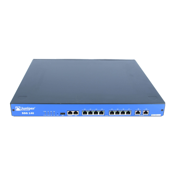
Page 9: Hardware Overview
Reset Pinhole Ethernet Ports Ports USB Port Console Port The following sections describe the elements on the front panel of the SSG 140 device: “Port Descriptions” on page 10 “Device Status LEDs” on page 11 “Ethernet Port LEDs” on page 12 “Reset Pinhole”... -
Page 10: Port Descriptions
SSG 140 Series Hardware Installation and Configuration Guide Port Descriptions Table 1 describes the function, connector type, and speed/protocol (if applicable) of the ports on the front panel of the SSG 140 device. Table 1: SSG 140 Ports Item Description... -
Page 11: Device Status Leds
Device Status LEDs The device LEDs show information about current device status. Figure 2 shows the position of each LED on the front of the SSG 140 device. Figure 2: Device Status LEDs When the device powers up, the POWER LED changes from off to green and the STATUS LED changes from off to blinking green. -
Page 12: Ethernet Port Leds
USB Port The USB port on the front panel of an SSG 140 device accepts a universal serial bus (USB) storage device. The USB ports let you transfer data such as device configurations, image keys, and ScreenOS software between a USB storage device and the internal flash storage of the security device. -
Page 13: Back Panel
STATUS STATUS PIM Slot 2 PIM Slot 4 The following sections describe the elements on the back panel of the SSG 140 device: “Physical Interface Module Slots” on page 13 “Power Switch” on page 14 “AC Power Appliance Inlet” on page 14 “Fuse Cover”... -
Page 14: Power Switch
The power switch is located on the right side of the back panel, as shown in Figure 5. You use the power switch to power the SSG 140 device on and off. When you power on the device, ScreenOS starts up as the power supply completes its startup sequence. -
Page 15: Installing And Connecting The Device
Chapter 2 Installing and Connecting the Device This chapter describes how to install an SSG 140 device in a standard 19-inch equipment rack and how to connect cables and power to the device. Topics in this chapter include: “Before You Begin” on page 16 “Installing Equipment”... -
Page 16: Before You Begin
Installing Equipment You can mount the SSG 140 device into a standard 19-inch equipment rack. You can center- or front-mount the device in a rack. Rack-mounting brackets are supplied with the device. - Page 17 Chapter 2: Installing and Connecting the Device To install an SSG 140 device into a rack: 1. Attach the mounting brackets to each side of the chassis as shown in Figure 6. For front mounting, use the holes nearest the front of the device. For center-mounting, use the holes nearest the center of each side of the device.
-
Page 18: Organizing Interface Cables
We recommend using a surge protector for the power connection. Powering the Device On and Off To power on the SSG 140 device, press the AC power switch on the rear panel to the on position. ScreenOS starts as the power supply completes its startup sequence. The POWER LED lights during startup and remains on steadily when the device is operating normally. - Page 19 Chapter 2: Installing and Connecting the Device 3. Connect an RJ-45 cable from the port labeled 0/2 (ethernet0/2 interface) to the external switch or router. The ethernet0/2 interface is prebound to the Untrust security zone. 4. Connect an RJ-45 cable from the Console port using the instructions provided in “Using a Console Connection”...
- Page 20 SSG 140 Series Hardware Installation and Configuration Guide Connecting the Device to a Network...
-
Page 21: Configuring The Device
Chapter 3 Configuring the Device ScreenOS software is preinstalled on the SSG 140 device. When the device is powered on, it is ready to be configured. While the device has a default factory configuration that allows you to initially connect to the device, you must perform further configuration for your specific network requirements. -
Page 22: Accessing The Device
SSG 140 Series Hardware Installation and Configuration Guide Accessing the Device You can configure and manage the SSG 140 device in several ways: Console—The Console port on the device lets you access the device through a serial cable connected to your workstation or terminal. To configure the device, you enter ScreenOS command line interface (CLI) commands on your terminal or in a terminal-emulation program on your workstation. - Page 23 Chapter 3: Configuring the Device 3. Plug the other end of the RJ-45 CAT5 cable into the Console port on the SSG 140. Figure 9 shows the arrangement of the cable and adapter. Figure 9: Establishing a Console Connection Serial port on...
-
Page 24: Using The Webui
SSG 140 Series Hardware Installation and Configuration Guide Using the WebUI To use the WebUI, the workstation from which you are managing the device must initially be on the same subnetwork as the device. To access the device with the WebUI: 1. -
Page 25: Default Device Settings
Note that the ethernet0/0 interface has the default IP address 192.168.1.1/24 and is configured for management services. If you connect the 0/0 port on the SSG 140 device to a workstation, you can configure the device from a workstation in the 192.168.1.1/24 subnetwork using a management service such as Telnet. -
Page 26: Basic Device Configuration
SSG 140 Series Hardware Installation and Configuration Guide Basic Device Configuration The following sections describe the basic configuration tasks required to place the SSG 140 device in operation. “Admin Name and Password” on page 26 “Administrative Access” on page 27 “Interface IP Address”... -
Page 27: Administrative Access
Chapter 3: Configuring the Device Administrative Access By default, anyone on your network who knows the login and password can manage your device. To configure a device to be managed only from a specific host on your network: WebUI Configuration > Admin > Permitted IPs: Enter the following, then click Add: IP Address/Netmask: ip_addr/mask set admin manager-ip ip_addr/mask save... -
Page 28: Hostname And Domain Name
SSG 140 Series Hardware Installation and Configuration Guide Hostname and Domain Name The domain name defines the network or subnetwork that the device belongs to, while the hostname refers to a specific device. The hostname and domain name together uniquely identify a device in the network. -
Page 29: Default Route
0.0.0.0/0 interface ethernet0/2 gateway ip_addr save Bridge Group Interfaces The SSG 140 device is pre-configured with bridge group (bgroup) interfaces identified as bgroup0/0 through bgroup0/2. Bgroups let you group multiple Ethernet interfaces together. Each bgroup constitutes its own broadcast domain and provides high-speed Ethernet switching between interfaces within the group. -
Page 30: Pim Configuration
For information about creating or modifying policies, refer to the Concepts & Examples ScreenOS Reference Guide. SSG 140 devices provide various detection methods and defense mechanisms to combat probes and attacks aimed at compromising or harming a network or network resource: ScreenOS Screen options secure a zone by inspecting, and then allowing or denying, all connection attempts that require crossing an interface to that zone. -
Page 31: Verifying External Connectivity
To verify that workstations in your network can access resources on the Internet, start a browser from any workstation in the network and browse to www.juniper.net/. Restarting the Device You may need to restart the device in order to implement new features, such as when you change between route and transparent mode or when you add new license keys. -
Page 32: Restarting The Device With The Webui
SSG 140 Series Hardware Installation and Configuration Guide 2. If you have not yet changed the default username and password, enter netscreen at both the login and password prompts. (Use lowercase letters only. The login and password fields are both case-sensitive.) 3. -
Page 33: Device Serial Number
Chapter 3: Configuring the Device NOTE: By default, the device recovery feature is enabled. You can disable it by entering the CLI unset admin device-reset command. Also, if the security device is in FIPS mode, the recovery feature is automatically disabled. You can restore the device to its default settings using one of these methods: Using the device serial number Using the CLI unset all command... -
Page 34: Reset Pinhole Button
SSG 140 Series Hardware Installation and Configuration Guide 2. At the command prompt, enter unset all. The following message is displayed: Erase all system config, are you sure y/[n] ? 3. Press y 4. Enter reset. Press n for the first question and y for the second question:... - Page 35 Chapter 3: Configuring the Device 3. Release the pinhole button, and wait two seconds. 4. Push the pinhole button again for four to six seconds. The message “2nd push has been confirmed” appears. 5. Continue to press the pinhole button until the device resets. The system now resets and returns to the login prompt;...
- Page 36 SSG 140 Series Hardware Installation and Configuration Guide Resetting the Device to Factory Defaults...
-
Page 37: Chapter 4 Servicing The Device
Tools and Parts Required To replace a component on an SSG 140 device, you need the following tools and parts: Electrostatic bag or antistatic mat Electrostatic discharge grounding wrist strap... -
Page 38: Replacing A Pim
SSG 140 Series Hardware Installation and Configuration Guide Replacing a PIM The SSG 140 device has four PIM slots in the back panel. PIMs are field installable and replaceable. CAUTION: Power off the device before removing or installing PIMs. PIMs are not hot-swappable. -
Page 39: Removing A Pim
Chapter 4: Servicing the Device Removing a PIM To remove a PIM: 1. Place an electrostatic bag or antistatic mat on a flat, stable surface on which you intend to place the PIM. 2. Attach an ESD grounding strap to your bare wrist, and connect the strap to an ESD point on the device. -
Page 40: Installing A Pim
10. Verify that the PIM status LED lights steadily green to confirm that the PIM is online. Upgrading Memory You can upgrade an SSG 140 device that has 256 MB of memory to 512 MB by replacing the 256 MB memory module with a 512 MB memory module. Ask your Juniper reseller for kit SSG-100-MEM-512. - Page 41 To determine the amount of memory, use the get sys command. The command response shows the amount of memory installed. NOTE: The SSG 140 device must have 512 MB of memory installed to run the following ScreenOS Unified Threat Management (UTM) features: Antivirus...
- Page 42 SSG 140 Series Hardware Installation and Configuration Guide Figure 12: Memory Module Slot Rear Memory module slot Front 10. Release the 256 MB memory module by pressing your thumbs downward on the locking tabs on each side of the module so that the tabs swivel away from 11.
-
Page 43: Replacing The Fuse
17. Replace the SSG 140 in the equipment rack. Replacing the Fuse The SSG 140 device uses a 6.3 amp fast acting fuse rated for 250 volts. To replace a failed fuse on the SSG 140 device: 1. Take the device off-line, turn the power switch OFF, and disconnect the power cable. - Page 44 SSG 140 Series Hardware Installation and Configuration Guide 3. Manually remove the fuse assembly from the device. 4. To replace the fuse assembly, enter the new fuse into the opening and slide it in until the fuse clicks into place.
-
Page 45: Appendix A Specifications
Appendix A Specifications This appendix provides general specifications for the SSG 140 device. It contains the following sections: “Physical” on page 45 “Electrical Specifications” on page 46 “Environmental Tolerance” on page 46 “Certifications” on page 47 “Connectors” on page 48 Physical Table 5 provides the physical specifications for the SSG 140 device. -
Page 46: Electrical Specifications
SSG 140 Series Hardware Installation and Configuration Guide Electrical Specifications Table 6 provides the electrical specifications for the SSG 140 device. Table 6: SSG 140 Electrical Specifications Item Specification AC input voltage Operating range: 90 to 264 VAC AC input line frequency... -
Page 47: Certifications
Appendix A: Specifications Certifications Table 8 provides the device certifications for the SSG 140 device. Table 8: SSG 140 Device Certifications Certification Type Certification Name Safety CAN/CSA-C22.2 No. 60950-1-03/UL 60950-1 Safety of Information Technology Equipment EN 60950-1 Safety of Information Technology Equipment... -
Page 48: Connectors
SSG 140 Series Hardware Installation and Configuration Guide Connectors Figure 15 shows the pin numbering of the RJ-45 connectors for the Console and AUX ports. Figure 15: RJ-45 Connector Pin Numbering Table 9 lists the pinouts of the RJ-45 connectors for the Console and AUX ports. - Page 49 Appendix A: Specifications Figure 16 shows the pin numbering of the connector on the DB-9 adapter supplied with the device. Figure 16: DB-9 Connector Pin Numbering Table 10 lists the pinouts for the DB-9 adapter. Table 10: DB-9 Adapter Pinouts DB-9 Pin RJ-45 Pin Name...
- Page 50 SSG 140 Series Hardware Installation and Configuration Guide The E1 and T1 PIMs use RJ-48 cables, which are not supplied with the PIM. Table 12 describe the RJ-48 connector pinouts. CAUTION: To maintain agency approvals, use only properly constructed, shielded cables.
-
Page 51: Appendix B Initial Configuration Wizard
Initial Configuration Wizard This appendix provides detailed information about the Initial Configuration Wizard (ICW) for an SSG 140 device. After you have physically connected your device to the network, you can use the ICW to configure the interfaces that are installed on your device. -
Page 52: Rapid Deployment Window
SSG 140 Series Hardware Installation and Configuration Guide 1. Rapid Deployment Window Figure 17: Rapid Deployment Window If your network uses Network and Security Manager (NSM), you can use a Rapid Deployment configlet to automatically configure the device. Obtain a configlet from your Security Manager administrator, select the Yes option, select the Load Configlet from: option, browse to the file location, then click Next. -
Page 53: Physical Ethernet Interface Window
Appendix B: Initial Configuration Wizard 3. Physical Ethernet Interface Window On the interface-to-zone bindings screen, you set the interface to which you want to bind the Untrust security zone. Ethernet0/0 is prebound to the Trust security zone. Ethernet0/1 is bound to the DMZ security zone but is optional. Ethernet0/2 is bound to the Untrust zone. -
Page 54: Untrust Zone Window
SSG 140 Series Hardware Installation and Configuration Guide 4. Untrust Zone Window The Untrust zone interface can have a static IP address or a dynamic IP address assigned via DHCP. Insert the desired information, then click Next. Figure 20: Untrust Zone Window... -
Page 55: Dmz Interface Ip Address Window
Appendix B: Initial Configuration Wizard 5. DMZ Interface IP Address Window Use this screen to configure an IP address and a netmask for the DMZ interface. Figure 21: DMZ Interface IP Address Window 6. Trust Interface IP Address Window Use this screen to configure an IP address and a netmask for the Trust interface. Figure 22: Trust Interface IP Address Window... -
Page 56: Physical Ethernet Dhcp Interface Window
SSG 140 Series Hardware Installation and Configuration Guide 7. Physical Ethernet DHCP Interface Window Select Yes to enable your device to assign IP addresses to your wired network via DHCP. Enter the IP address range that you want your device to assign to clients using your network, then click Next. -
Page 57: Confirmation Window
Appendix B: Initial Configuration Wizard 8. Confirmation Window Confirm your device configuration and change as needed. Click Next to save, restart the device, and run the configuration. Figure 24: Confirmation Window After the device restarts with the saved system configuration, the WebUI login prompt appears. - Page 58 SSG 140 Series Hardware Installation and Configuration Guide...
-
Page 59: Index
Index EMC certifications ............47 emissions certifications access, configuring administrative ..........47 ......27 environmental specifications addresses, default IP .............25 ........46 equipment racks, installing admin name and password, changing ...........16 ......26 administrative access, configuring ......27 ALARM LED ..............11 faceplates, removing .............38 factory defaults, resetting to .........32 back-panel components ..........13... - Page 60 SSG 140 Hardware Installation and Configuration Guide power, connecting ............18 racks, installing .............. 16 removing faceplates ..............38 PIMs ................39 Reset/Reset Config button ..........34 resetting to factory defaults .......... 32 restarting the device ............31 routes, configuring default ...........
Need help?
Do you have a question about the SSG 140 and is the answer not in the manual?
Questions and answers