
Subscribe to Our Youtube Channel
Related Manuals for MEIG SLM 320


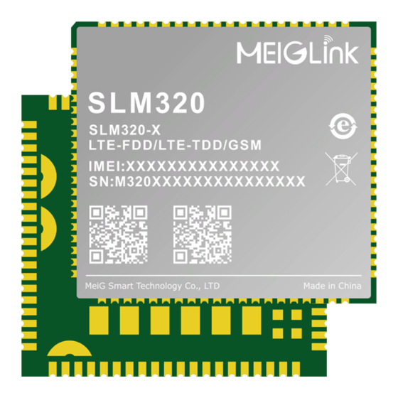
Summary of Contents for MEIG SLM 320
- Page 1 MeiG_SLM320_Hardware Design Manual Controlled Version Number: V1.2 Release date:2021-06-18...
-
Page 2: Important Notice
Copyright Notice All rights reserved. MeiG Smart Technology Co., Ltd This manual and all its contents are owned by MeiG Smart Technology Co., Ltd and protected by Chinese laws and relevant copyright laws in applicable international conventions. Without the written authorization of MeiG Smart Technology Co., Ltd, no one may copy, disseminate, distribute, modify or use part or all of this manual in any form, and the offenders will be held responsible according to law. -
Page 3: Revision History
MeiG_SLM320_Hardware Design Manual Revision History Revision Date Description V1.0 2020-04-21 First edition V1.1 2021-04-22 Modify file format and correct description Update SLM320-LA frequency information added V1.2 2021-06-18 performance for B2/B4 MeiG Smart Technology Co., Ltd 2/89... -
Page 4: Table Of Contents
3.13 USB_BOOT Port ........................37 GNSS Receiver ..........................38 General Description ........................ 38 GNSS Performance ........................ 38 Layout Guidelines ........................38 Antenna connection ........................ 38 Antenna interface..........................39 Introduction to Antenna Interface ................... 39 MeiG Smart Technology Co., Ltd 3/89... - Page 5 Storage ............................ 83 Reflow Profile .......................... 83 Packaging ..........................84 Appendix A refers to documentation and term abbreviations ..........85 Reference File ......................... 85 Symbol Key ..........................85 10 Appendix B GPRS Coding Scheme ....................89 MeiG Smart Technology Co., Ltd 4/89...
-
Page 6: Introduction
SLM320 not only provides wireless data access, but also provides voice mesdrope and other functions. SLM320 can be widely used in the field of M2M, such as OBD, CPE, router, data card, DTU, security and industrial PDA, etc. MeiG Smart Technology Co., Ltd 5/89... -
Page 7: Safety Instruction
Keep mobile devices away from flammable gases. When you are near a gas station, oil depot, chemical plant or explosion site, turn off mobile terminals. Operating electronic devices in any potentially explosive site is a safety hazard. MeiG Smart Technology Co., Ltd 6/89... -
Page 8: Product Overview
Class 1 (30dBm±2dB) for DCS1800 PCL0 Class E2 (27dBm±3dB) for GPRS900 PCL8 Transmitted power Class E2 (26dBm±3dB) for GPRS1800 PCL2 Class 3 (23dBm±2.7dB) for FDD-LTE bands Class 3 (23dBm±2.7dB) for TDD-LTE bands MeiG Smart Technology Co., Ltd 7/89... - Page 9 To develop debug, the log output Baud rate is default115200bps Conforms to SD3.0 protocol Interface Comply with 3GPP TS 27.007, 27.005, and MeiG AT Commands enhanced AT command NET_STATUS,NET_MOD these two pins indicate the Network Indicator state of the network MeiG Smart Technology Co., Ltd...
- Page 10 LCC Functional Interface Indicator interface Keyboard interface Sleep control interface Flight mode control interface ADC interface I2C interface SPI interface SD interface USB_BOOT port MeiG Smart Technology Co., Ltd 9/89...
-
Page 11: Functional Block Diagram
MeiG_SLM320_Hardware Design Manual Functional block diagram Following is the functional block diagram of SLM320, illustrating its main functions. Internal memory The radio frequency part peripheral interface Figure 1 Functional block diagram MeiG Smart Technology Co., Ltd 10/89... -
Page 12: Evaluation Kit
MeiG_SLM320_Hardware Design Manual Evaluation Kit To facilitate testing and use of the SLM320 module, MeiG provides an evaluation Kit to customer. Evaluation Kit includes USB cables, antennas, and other peripherals. Please refer to the specific use method of evaluation board MeiG_SLM320_Mini PCIe_EVB_UGD MeiG Smart Technology Co., Ltd... -
Page 13: Application Interface
Hardware reset interface Pilot light interface Keyboard interface Sleep control interface Flight mode control interface ADC port I2C port SPI port SD port USB_BOOT port MeiG Smart Technology Co., Ltd 12/89... -
Page 14: Pin Assignment
MeiG_SLM320_Hardware Design Manual Pin Assignment The following figure shows the pin assignment of SLM320 module. Figure 2 Pin Assignment Note: The pin name in the pin diagram is the actual wiring name inside the module. MeiG Smart Technology Co., Ltd 13/89... -
Page 15: Pin Description
GPIO30 VIHnom=1.8V If not, please suspend this pin Systematic sleep VOLnom=0V indicator SLEEP_IND GPIO8 VOHnom=1.8V If not, please suspend this pin Modular flight mode VILnom=0V W_DISABLE# controlIf not, please GPIO31 VIHnom=1.8V suspend this pin MeiG Smart Technology Co., Ltd 14/89... - Page 16 USIM data signal line USIM_CLK 1.8V/3.0V USIM clock signal line USIM_RST 1.8V/3.0V USIM reset signal line The module is internally VILnom=0V If not, please suspend connected GPIO18 VIHnom=1.8V this pin with UART2_ RTS, default MeiG Smart Technology Co., Ltd 15/89...
- Page 17 If not, please suspend this pin SDC2_CLK SDC2_CLK 1.8V/3.0V If not, please suspend this pin SDC2_CMD SDC2_CMD 1.8V/3.0V If not, please suspend this pin SD card pull-up power VDD_SDIO 1.8V/3.0V supply, power supply capacity 150mA MeiG Smart Technology Co., Ltd 16/89...
- Page 18 If not, please suspend this pin ADC interface 0 When in use, 1K in ADC0 series, If not, please suspend this pin GPS antenna ANT_GNSS If not, please suspend this pin ANT_MAIN Main collector antenna MeiG Smart Technology Co., Ltd 17/89...
- Page 19 The module receives UART_2_RX UART_2_RXD VOHnom=1.8V data Module sends data UART1_ TXD, VOLnom=0V If not, please suspend for at MAIN_TXD VOHnom=1.8V this pin command VILnom=0V The module receives UART1_ MAIN_RXD VIHnom=1.8V data RXD, for at MeiG Smart Technology Co., Ltd 18/89...
- Page 20 Keyboard matrix input VILnom=0V signal KEYIN4 VIHnom=1.8V If not, please suspend this pin Keyboard matrix input VILnom=0V signal KEYIN5 VIHnom=1.8V If not, please suspend this pin VOLnom=0V Keyboard matrix input KEYOUT0 VOHnom=1.8V signal MeiG Smart Technology Co., Ltd 19/89...
- Page 21 1.8V/3.0V If not, please suspend this pin SPILCD_SEL SPILCD_SEL 1.8V/3.0V If not, please suspend this pin SPILCD_CS SPILCD_CS 1.8V/3.0V If not, please suspend this pin SPILCD_CLK SPILCD_CLK 1.8V/3.0V If not, please suspend this pin MeiG Smart Technology Co., Ltd 20/89...
- Page 22 VILnom=0V UART3_RXD If not used, suspend this VIHnom=1.8V UART3_ TXD, VOLnom=0V UART3_TXD If not used, suspend this VOHnom=1.8V Reserve CLK of camera Configurable as GPIO REF_CLK If not used, suspend this 140* RESERVED RESERVED MeiG Smart Technology Co., Ltd 21/89...
-
Page 23: Power Source
Table 5 Description of SLM320 module power interface. Pin Name Description Module power supply, 3.4~4.5V, nominal VBAT_RF 57,58 value 3.8 Module power supply, 3.4~4.5V, nominal VBAT_BB 59,60 value 3.8 VDD_EXT Voltage output, 1.8V 8,9,19,22,36,46,48,50-5 4,56,85-112 MeiG Smart Technology Co., Ltd 22/89... -
Page 24: Power Supply
VBAT_BB and VBAT_RF need to adopt star wiring. VBAT_BB wire width shall not be less than 1mm, and VBAT_RF wire width shall not be less than 2mm. In principle, the longer the line in VBAT, the wider MeiG Smart Technology Co., Ltd 23/89... -
Page 25: Power Supply Reference Circuit
1.8V, and the current load is 50mA. This output voltage can be used as an external pull-up source, such as a level reference, and the Pin status can be read to determine whether the module is switched on or not. MeiG Smart Technology Co., Ltd 24/89... -
Page 26: Start Up
The boot sequence is shown in the figure below: NOTE VBAT ≥500ms 1.6V ≥ PWRKEY ≤0.3V 2 ms ≥ VDD_EXT RESET_N ≥2.5s ( OD ) STATUS ≥ 10s UART I nactive Active ≥ 13s I nactive Active Figure8 Power-on sequence diagram MeiG Smart Technology Co., Ltd 25/89... -
Page 27: Power Off
When the module is working, user can pull down the RESET_N pin by at least 150ms to reset the module. RESET_N signal is sensitive to interference, so it is suggested that the routing should be as short as possible and should be protected by GND traces. MeiG Smart Technology Co., Ltd 26/89... -
Page 28: At Command Reset
The reset sequence diagram is as follows: VBAT ≥150ms ≥1.6V RESET_N ≤0.3V Figure 11 RESET_N reset sequence diagram 3.6.2 AT command Reset Through SLM320 UART or USB AT port, enter AT+TRB command, make SLM320 reset and restart. MeiG Smart Technology Co., Ltd 27/89... -
Page 29: Usim/Sim Interface
SIM card is pulled out, then the SIM card is not read. SIM0_ Det is valid in high level by default and can be switched to low level by AT command. MeiG Smart Technology Co., Ltd 28/89... - Page 30 100mm; In order to prevent USIM_CLK signals from crosstalk with USIM_DATA, the two wires should not be too close together and an additional shielding should be added between the two wires; MeiG Smart Technology Co., Ltd 29/89...
-
Page 31: Usb Port
In order to meet the signal integrity requirement of USB data line, R1/R2/R3/R4 resistors must be placed close to the module and between resistors close to each other. The branch connecting the test point must be as short as possible. MeiG Smart Technology Co., Ltd 30/89... -
Page 32: Serial Port
Table 10 Main serial port pin description Pin Name Description UART1_RING Module output ring prompt UART2_TXD Module sends data Module clear send The module requests to send MAIN_TXD Module sends data MAIN_RXD The module receives data MeiG Smart Technology Co., Ltd 31/89... - Page 33 TI's TXB0104PWR is recommended. The following picture is a reference design: VDD_EXT VDD_MCU VCCA VCCB 0.1uF 0.1uF RI_MCU DCD_MCU CTS_MCU Translator RTS_MCU DTR_MCU TXD_MCU RXD_MCU DSR_MCU Figure 15 Level conversion chip reference circuit MeiG Smart Technology Co., Ltd 32/89...
-
Page 34: 3.10 Status Indication
MODE,NET_ Status and status (reserved, default NC) are three network status pins. The following two tables describe pin definitions and logic level changes in different network states. Table 13 Description of network indicator pin Pin Name Describe NET_MODE Module status indication NET_STATUS Module status indication STATUS Reserved MeiG Smart Technology Co., Ltd 33/89... - Page 35 Status is used to indicate the working status of the module, which is an open drain output pin. The customer can connect this pin to the GPIO or GPIO of the device band pull-up. MeiG Smart Technology Co., Ltd 34/89...
-
Page 36: 3.11 Low Power Mode
At + CSCLK = 0: close deep sleep function. At + CSCLK =1: when setting, DTR pin needs to be high level, or wakeup pin needs to be low level to enter deep sleep mode; MeiG Smart Technology Co., Ltd 35/89... -
Page 37: Ultra Low Power Mode
In the case that VBAT is not powered, the ADC interface cannot directly connect any input voltage. It is recommended that the ADC pin be input with voltage divider circuit. It is suggested that ADC should be wrapped when wiring, which can improve the accuracy of ADC voltage measurement. MeiG Smart Technology Co., Ltd 36/89... -
Page 38: 3.13 Usb_Boot Port
USB interface. Table 18 USB_BOOT pin definition Pin Name Description Short connect USB_BOOT and VDD_EXT USB_BOOT (V_IO18) before starting the module, and then the module will VDD_EXT enter the forced download mode MeiG Smart Technology Co., Ltd 37/89... -
Page 39: Gnss Receiver
Customers can use active antenna and passive antenna. If customers use active antenna, please refer to the figure below, if passive antenna is used, please refer to the figure (Figure 19 RF reference circuit) MeiG Smart Technology Co., Ltd 38/89... -
Page 40: Antenna Interface
Schematic design, redundant RF connectors between the RF port of the module and the antenna, used for certification test, RF connectors are not attached after mass production and delivery; (Reference: RF Connector -1P-H176); Schematic design, type matching circuit is reserved near the antenna end, capacitor is not affixed MeiG Smart Technology Co., Ltd 39/89... -
Page 41: Installation Of Antenna
(dBi): 1 Maximum Inupt (W): 2W Input impedance (ohm): 50 GSM/TDD-LTE/FDD-LTE Polarization Type: vertical direction Cable insertion loss: < 1.5dB (GSM900/1800 ; LTE B1/B2/B3/B4/B5/B8/B34/B39) Cable insertion loss: < 2dB (LTE B7/B38/B40/B41) WIFI/BT VSWR: < 2 MeiG Smart Technology Co., Ltd 40/89... -
Page 42: Rf Output Power
30dBm±2dB 0dBm±5dB LTE-FDD B1 23dBm±2.7dB <-39dBm LTE-FDD B2 23dBm±2.7dB <-39dBm LTE-FDD B3 23dBm±2.7dB <-39dBm LTE-FDD B4 23dBm±2.7dB <-39dBm LTE-FDD B5 23dBm±2.7dB <-39dBm LTE-FDD B7 23dBm±2.7dB <-39dBm LTE-FDD B8 23dBm±2.7dB <-39dBm LTE-FDD B20 23dBm±2.7dB <-39dBm MeiG Smart Technology Co., Ltd 41/89... -
Page 43: Rf Reception Sensitivity
-98dBm -94.3dBm LTE-FDD B7 -97dBm -94.3dBm LTE-FDD B8 -98dBm -93.3dBm LTE-FDD B20 -98dBm -93.3dBm LTE-FDD B28 -98dBm -94.8dBm LTE-TDD B34 -97.5dBm -96.3dBm LTE-TDD B38 -97.5dBm -96.3dBm LTE-TDD B39 -97.5dBm -96.3dBm LTE-TDD B40 -97.5dBm -96.3dBm MeiG Smart Technology Co., Ltd 42/89... -
Page 44: Working Frequency
2500~2570 2620~2690 LTE-FDD B8 880~915 925~960 LTE-FDD B20 832~862 791~821 LTE-FDD B28 703~748 758~803 LTE-TDD B34 2010~2025 2010~2025 LTE-TDD B38 2570~2620 2570~2620 LTE-TDD B39 1880~1920 1880~1920 LTE-TDD B40 2300~2400 2300~2400 LTE-TDD B41 2555~2655 2555~2655 MeiG Smart Technology Co., Ltd 43/89... - Page 45 MeiG_SLM320_Hardware Design Manual WIFI/BT 2400-2483 2400~2483 1575.42±1 1559~1563 Glonass 1597~1606 MeiG Smart Technology Co., Ltd 44/89...
-
Page 46: Ota Antenna Requirements
<1.6W/Kg <-94 Band2 <-94 Band3 <-94 Band4 <-94 FDD-LTE Band5 <-94 Band7 <-94 Band8 <-94 Band20 <-94 Band28 <-94 WIFI 2400 <2.5:1 >0dBi >-4dBi >40% <1.6W/Kg <-80 2400 <2.5:1 >0dBi >-4dBi >40% <1.6W/Kg <-82 MeiG Smart Technology Co., Ltd 45/89... -
Page 47: Electrical Characteristics
Electrical Characteristics of Interface Working State :Logic low level :Logic high level Table 26 The logic level of a normal digital IO signal Signal Unit digital input -0.3 digital output 0.45 1.35 MeiG Smart Technology Co., Ltd 46/89... -
Page 48: Module Power Consumption Range
The tested module was powered on, and the data network was successfully registered; Set the module to sleep state through AT instruction (USB is in suspended state) Under the condition of no data MeiG Smart Technology Co., Ltd 47/89... - Page 49 Set the module to sleep state through AT instruction (USB is in suspended state); Under the condition of no data transmission, the tested module maintained for 10 minutes and recorded the average current for 10 minutes. MeiG Smart Technology Co., Ltd 48/89...
- Page 50 Under the condition of no data transmission, the tested module maintained for 10 minutes and recorded the average current for 10 minutes. PCS CH512 The tested module was powered on, and the data network was successfully registered; MeiG Smart Technology Co., Ltd 49/89...
- Page 51 Band1 CH18550 The tested module was powered on, and the data network was successfully registered; Set the module to sleep state through AT instruction (USB is in suspended state); Under the condition of no data MeiG Smart Technology Co., Ltd 50/89...
- Page 52 Set the module to sleep state through AT instruction (USB is in suspended state); Under the condition of no data transmission, the tested module maintained for 10 minutes and recorded the average current for 10 minutes. MeiG Smart Technology Co., Ltd 51/89...
- Page 53 Under the condition of no data transmission, the tested module maintained for 10 minutes and recorded the average current for 10 minutes. Band4 CH20375 The tested module was powered on, and the data network was successfully registered; MeiG Smart Technology Co., Ltd 52/89...
- Page 54 Band8 CH21625 The tested module was powered on, and the data network was successfully registered; Set the module to sleep state through AT instruction (USB is in suspended state); Under the condition of no data MeiG Smart Technology Co., Ltd 53/89...
- Page 55 Set the module to sleep state through suspended AT instruction (USB is in suspended state state); Under the condition of no data transmission, the tested module maintained for 10 minutes and recorded the average current for 10 minutes. MeiG Smart Technology Co., Ltd 54/89...
- Page 56 10 minutes. The module is Band1 CH18300 powered on, Under the condition of no data standby 38.39 and the DRX transmission, the tested module monitoring maintained for 10 minutes and recorded MeiG Smart Technology Co., Ltd 55/89...
- Page 57 10 minutes and recorded the average current for 10 minutes. Band4 CH20175 Under the condition of no data transmission, the tested module 39.5 maintained for 10 minutes and recorded the average current for 10 minutes. MeiG Smart Technology Co., Ltd 56/89...
- Page 58 10 minutes and recorded monitoring the average current for 10 minutes. period of the idle state on Band40 CH39150 the network is Under the condition of no data 38.94 1.28s transmission, the tested module MeiG Smart Technology Co., Ltd 57/89...
- Page 59 The tested module carries out data set at 3.8V; transmission and maintains for 5 minutes, 525.95 and records the average current for 5 minutes Band1 23dBm CH18050 590.36 The tested module carries out data MeiG Smart Technology Co., Ltd 58/89...
- Page 60 5 minutes, 258.21 and records the average current for 5 minutes Band3 23dBm CH19575 The tested module carries out data transmission and maintains for 5 minutes, 650.21 and records the average current for 5 minutes MeiG Smart Technology Co., Ltd 59/89...
- Page 61 The tested module carries out data transmission and maintains for 5 minutes, 209.25 and records the average current for 5 minutes Band5 23dBm CH20525 The tested module carries out data 543.21 transmission and maintains for 5 minutes, MeiG Smart Technology Co., Ltd 60/89...
- Page 62 5 minutes, 174.21 and records the average current for 5 minutes Band8 10dBm The tested module carries out data transmission and maintains for 5 minutes, 214.3 and records the average current for 5 minutes MeiG Smart Technology Co., Ltd 61/89...
- Page 63 The tested module carries out data transmission and maintains for 5 minutes, 388.39 and records the average current for 5 minutes Band40 10dBm The tested module carries out data 165.22 transmission and maintains for 5 minutes, MeiG Smart Technology Co., Ltd 62/89...
- Page 64 Real Insert the mobile card, the actual network standby, use the Dormant network AT command to query the registration on the network, and Sleep record the average current of 10 minutes。 MeiG Smart Technology Co., Ltd 63/89...
- Page 65 Set the module to sleep state through GSM900 AT instruction (USB is in suspended state); Under the condition of no data transmission, the tested module maintained for 10 minutes and recorded MeiG Smart Technology Co., Ltd 64/89...
- Page 66 AT instruction (USB is in suspended state); 3Under the condition of no data transmission, the tested module maintained for 10 minutes and recorded the average current for 10 minutes. DCS CH885 The tested module was powered on, MeiG Smart Technology Co., Ltd 65/89...
- Page 67 The tested module was powered on, and the DRX and the data network was successfully monitoring registered; period of the Set the module to sleep state through idle state on AT instruction (USB is in suspended MeiG Smart Technology Co., Ltd 66/89...
- Page 68 Set the module to sleep state through AT instruction (USB is in suspended state); Under the condition of no data transmission, the tested module maintained for 10 minutes and recorded MeiG Smart Technology Co., Ltd 67/89...
- Page 69 AT instruction (USB is in suspended state); Under the condition of no data transmission, the tested module maintained for 10 minutes and recorded the average current for 10 minutes. Band4 CH20000 The tested module was powered on, MeiG Smart Technology Co., Ltd 68/89...
- Page 70 10 minutes. Band5 CH20525 The tested module was powered on, and the data network was successfully registered; Set the module to sleep state through AT instruction (USB is in suspended MeiG Smart Technology Co., Ltd 69/89...
- Page 71 Set the module to sleep state through AT instruction (USB is in suspended state); Under the condition of no data transmission, the tested module maintained for 10 minutes and recorded MeiG Smart Technology Co., Ltd 70/89...
- Page 72 AT instruction (USB is in suspended state); Under the condition of no data transmission, the tested module maintained for 10 minutes and recorded the average current for 10 minutes. Band4 CH20350 The tested module was powered on, MeiG Smart Technology Co., Ltd 71/89...
- Page 73 10 minutes. Band7 CH21400 The tested module was powered on, and the data network was successfully registered; Set the module to sleep state through AT instruction (USB is in suspended MeiG Smart Technology Co., Ltd 72/89...
- Page 74 Set the module to sleep state through AT instruction (USB is in suspended state); Under the condition of no data transmission, the tested module maintained for 10 minutes and recorded MeiG Smart Technology Co., Ltd 73/89...
- Page 75 AT instruction (USB is in suspended state); Under the condition of no data transmission, the tested module maintained for 10 minutes and recorded the average current for 10 minutes. Band28 CH27610 The tested module was powered on, MeiG Smart Technology Co., Ltd 74/89...
- Page 76 10 minutes. Band39 CH38300 The tested module was powered on, and the data network was successfully registered; Set the module to sleep state through AT instruction (USB is in suspended MeiG Smart Technology Co., Ltd 75/89...
- Page 77 Set the module to sleep state through AT instruction (USB is in suspended state); Under the condition of no data transmission, the tested module maintained for 10 minutes and recorded MeiG Smart Technology Co., Ltd 76/89...
- Page 78 Set the module to sleep state through AT instruction (USB is in suspended state); Under the condition of no data transmission, the tested module maintained for 10 minutes and recorded the average current for 10 minutes. MeiG Smart Technology Co., Ltd 77/89...
-
Page 79: Environmental Reliability Requirements
Refer to the following table for the discharge range allowed by ESD for SLM320 module. Table 30 ESD performance parameters (temperature: 25℃, humidity: 45%) Test point Contact discharge Units Test point MeiG Smart Technology Co., Ltd 78/89... - Page 80 MeiG_SLM320_Hardware Design Manual ±4 Antenna interface ±4 Antenna interface MeiG Smart Technology Co., Ltd 79/89...
-
Page 81: Mechanical Characteristics
This section describes the mechanical dimensions of the module, all in millimeters; All dimensions not marked with tolerance, tolerance is ±0.05mm. Module Mechanical Dimensions Figure 20 Module top and side dimensions (unit: mm) a. Bottom view size MeiG Smart Technology Co., Ltd 80/89... -
Page 82: Recommended Footprint
MeiG_SLM320_Hardware Design Manual b. Bottom view size Figure 21 bottom view dimension (unit: mm) Recommended Footprint Figure 22 Recommended package (top view) (unit: mm) MeiG Smart Technology Co., Ltd 81/89... -
Page 83: Top View Of Module
MeiG_SLM320_Hardware Design Manual Top View of Module Figure 23 Top view of the module Bottom View of Module Figure 24 Bottom view of the module MeiG Smart Technology Co., Ltd 82/89... -
Page 84: Storage And Production
If the module needs to be baked, bake at 125℃ (fluctuation of 5℃ above and below) for 8 hours. Note: The module packaging cannot withstand such high temperature, please remove the module packaging before the module baking. Reflow Profile Figure 25 Reflow temperature curve MeiG Smart Technology Co., Ltd 83/89... -
Page 85: Packaging
MeiG_SLM320_Hardware Design Manual Packaging SLM320 adopts tray packaging, shown as below: Figure 26 SLM320 in tray packaging MeiG Smart Technology Co., Ltd 84/89... -
Page 86: Appendix A Refers To Documentation And Term Abbreviations
Peripheral Component Interconnect Circuit Switched (CS) domain Circuit Switched Data Data communication equipment Data terminal equipment Data Terminal Ready EDGE Enhanced Data rates for GSM Evolution Enhanced Full Rate EGSM Enhanced GSM Electromagnetic Compatibility MeiG Smart Technology Co., Ltd 85/89... - Page 87 International Mobile Equipment Identity MEID Mobile Equipment Identifier Input/Output International Standards Organization International Telecommunications Union bits per second Light Emitting Diode Machine to machine Mobile Originated Mobile Terminated Negative Temperature Coefficient Personal Computer Printed Circuit Board MeiG Smart Technology Co., Ltd 86/89...
- Page 88 Vmin Minimum Voltage Value Maximum Input High Level Voltage Value Minimum Input High Level Voltage Value Maximum Input Low Level Voltage Value Minimum Input Low Level Voltage Value Maximum Output High Level Voltage Value MeiG Smart Technology Co., Ltd 87/89...
- Page 89 MeiG_SLM320_Hardware Design Manual Minimum Output High Level Voltage Value Maximum Output Low Level Voltage Value Minimum Output Low Level Voltage Value MeiG Smart Technology Co., Ltd 88/89...
-
Page 90: 10 Appendix B Gprs Coding Scheme
-Consult the dealer or an experienced radio/TV technician for help. Body-worn Operation This equipment complies with FCC radiation exposure limits set forth for an uncontrolled environment. This equipment should be installed and operated withmini mum distance 20cm between the radiator & your body. MeiG Smart Technology Co., Ltd 89/89... - Page 91 C.Appendix A A1.Requirement of FCC KDB 996369 D03 for module certification: 1.1List of applicable FCC rules: The module complies with FCC Part 2,22,24,27 1.2Summarize the specific operational use conditions: SLM320 use the independent GPS chip,includes a fully integrated global navigation satellite system solution that supports GPS, GLONASS, BeiDou.
- Page 92 This equipment complies with FCC radiation exposure limits set forth for an uncontrolled environment. This equipment should be installed and operated withmini mum distance 20cm between the radiator & your body The host product Labeling Requirements: NOTICE: The host product must make sure that FCC labeling requirements are met. This includes clearly visible exterior label on the outside of the final product housing that displays the contents shown in below: Contains FCC ID:2APJ4-SLM320-L...
Need help?
Do you have a question about the SLM 320 and is the answer not in the manual?
Questions and answers