Table of Contents
Advertisement
Quick Links
greater. If you do not currently have this viewer installed on your
i
ON Media is a registered trademark of Carver Professional, A Phoenix Gold International Company
AMX, PANJA and Crestron are the registered trademarks of their respective owners.
Rev 04.08.021
CV Series
User Manual
User Manual
User Manual
User Manual
This User Manual is made available in Adobe Acrobat format.
In order to view the manual and utilize it's enhancements we
recommend that you download Adobe Acrobat Reader® 4.0 or
computer, or you have an older version the reader is available
as a free download at http://www.adobe.com.
By going to the table of contents you can directly access any
topic outlined there, by simply clicking on the topic.
© Phoenix Gold International, Inc. February 2001
- 1 –
Advertisement
Table of Contents

Subscribe to Our Youtube Channel
Related Manuals for Carver CV Series


Summary of Contents for Carver CV Series
- Page 1 By going to the table of contents you can directly access any topic outlined there, by simply clicking on the topic. ON Media is a registered trademark of Carver Professional, A Phoenix Gold International Company AMX, PANJA and Crestron are the registered trademarks of their respective owners.
-
Page 2: Table Of Contents
10-14 Input Wiring Input Sensitivity Loudspeaker Polarity Mono Operation Bridged Mono Connections Power Sequencing Remote Level Control Effects Loop CV Series Block Diagram 12-13 Warranty Information In Case Of Difficulty Appendix A Appendix B - 2 – 15-16 16-17 18-20... -
Page 3: Unpacking And Paperwork
Purchased at: __________________________ Date: _________________ Finally, take a moment to fill out the Warranty Registration Card packed with the amplifier and return it to Carver Professional. This will allow us to keep you informed about new products, as they become available Rev 04.08.021... -
Page 4: Cv1501
CV1501 Power Output • 150W mono into 4 ohm and 8 ohm loads, autoformer coupled, 40Hz to 20kHz ±3db with < 0.5% THD at full power • 150W mono transformer coupled @ 25V, 35V, 50V, 70V and 100V 40Hz to 18kHz ±3dB with <... -
Page 5: Cv1501
SPECIFICATIONS with Basic input module PERFORMANCE: • • • • THD: • • • • IMD DIM30 Method: • • • • Dynamic Headroom: • • • • Power Bandwidth: • • • • Frequency Response: • • • • Signal-to-Noise: •... -
Page 6: Cv1502
CV1502 Power Output • 150W per channel into 4 ohm and 8 ohm loads, autoformer coupled, 40Hz to 20kHz ±3dB with < 0.5% THD at full power • 150W per channel, transformer coupled @ 25V, 35V, 50V, 70V and 100V, 40Hz to 18kHz ± 3dB with <... - Page 7 SPECIFICATIONS with Basic input module PERFORMANCE: • THD: • • • • IMD DIM30 Method: • • • • Dynamic Headroom: • • • • Power Bandwidth: • • • • Frequency Response: • • • • Signal-to-Noise • • • • Crosstalk: •...
-
Page 8: Cv4002
CV4002 Power Output • 400W per channel into 4 ohm and 8 ohm loads, autoformer coupled, 40Hz to 20kHz ±3dBwith < 0.5% THD at full power • 400W per channel, transformer coupled @ 25V, 35V, 50V, 70V and 100V, 40Hz to 18kHz ±3dB with < 0.5% THD at full power •... -
Page 9: Cv4002
SPECIFICATIONS with Basic input module PERFORMANCE: • THD: • • • • IMD DIM30 Method: • • • • Dynamic Headroom: • • • • Power Bandwidth: • • • • Frequency Response: • • • • Signal-to-Noise • • • • Crosstalk: •... -
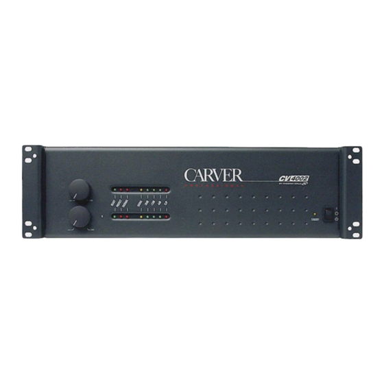
Page 10: Controls And Functions
2. Level Controls The Level Controls on the CV Series amplifiers utilize a DC voltage to control the output level of the CV Series amplifiers through a VCA (voltage controlled amplifier). The knobs can be removed and replaced with black plastic caps provided with the amplifier. -
Page 11: Power Switch
The digits preceding the last digit designate the rated output power of a channel or zone for that amplifier. The CV Series amplifiers are a constant voltage design, and have the same output at 4 ohm, 8 ohm, 25V, 35V, 50V, 70V and 100V taps. Thus a CV1502 has two channels or zones each rated at 150 watts per channel at any selected tap. -
Page 12: Output Connector
The Serial Number is used by Carver Professional to track units and establish their warranty status. Be sure to record the serial number of all Carver Professional units, and to keep those records in a safe and secure location for future reference. Never remove the serial number, as this will void the warranty. -
Page 13: Remote Level Control
8. AC Line Cord Receptacle An IEC type AC line cord receptacle is provided to receive the line cord included with the CV Series amplifier. An appropriate line cord termination is provided based on the country of destination with each Rev 04.08.021... -
Page 14: Configuration Dip Switch
(Note: The signal at the Send Pins of the Effects Loop are post any signal processing performed by a optional input module that may be in use in the CV Series amplifier). Connections to the Effects Loop are intended to be local, and signals sent over long wire runs are not recommended. -
Page 15: Thermal Considerations
A minimum space of 1U should be left between CV Series amplifiers at no more than a 12U interval. This should allow sufficient cooling of the amplifiers. If the CV Series amplifiers are mixed with other devices, caution should be taken to locate the CV Series amplifiers together, facilitating the chimney effect of their heatsink design. -
Page 16: Input Sensitivity
Another input to the CV Series amplifiers is provided via the EFX Loop’s RCV (receive) input. This input is only available when the FX Loop is enabled on the DIP switch located on the rear of the amplifier. This input is designed for unbalanced line level input only, and should only be used with equipment that is local to the CV amplifier or rack containing the CV amplifier, such as, an outboard signal processing device or the SND output from the FX Loop on the same or another (local) CV amplifier. -
Page 17: Bridged Mono Connections
500 watts. (See Figure 8) It is also necessary to connect the commons together when bridging a distributed load. Caution: A 4 ohm mono load should not be connected to the CV Series amplifier in the bridged mode, but you can use the parallel mono configuration with a 4 ohm load. -
Page 18: Power Sequencing
Important Note: When bridging the CV Series amplifier at one of the distributed voltage outputs, it is necessary to connect the Common connections for the distributed voltages together. The commons on the secondary side of the output transformers are floating. This is not true for the low-impedance outputs. -
Page 19: Ground Test Procedure
0.2 ohms we recommend that you connect the chassis ground terminals of the sequence connector together in a daisy chain as in Figure 12. Repeat this for each CV Series amplifier in the rack. If there is less than a 0.2 ohm resistance from the rail to the chassis ground of each unit you do not have to daisy chain the chassis grounds together. -
Page 20: Remote Level Control
Using Other Amplifiers in the Power Sequence The Carver pm700, pm950, pm1400, pt1800 and pt 2400 can be use together with the CV Series amplifiers in a “Sequenced” configuration. However, as the Sequence Terminal on the pm Series has no... - Page 21 As an added bonus, low current loads, such as an LED, may be connected between the +5V and RTN terminals. This may be useful if one desires a visual indication that the CV Series amplifier is powered ON. The +5V at the “Remote Level”...
-
Page 22: Remote Level Control
A/V Systems. A voltage ramp provided by one of these manufacturers, and controlled by their system can be used to adjust level on the CV Series amplifiers. Apply a control voltage from the external source of the desired control system to the “Remote Level” input terminal. This voltage may be applied to either or both of the CV1 and CV2 input terminals. -
Page 23: Warranty Information
Carver Professional. We suggest that you attach your purchase receipt to this Warranty and keep both documents in a safe place. Thank you for your choice of a Carver Professional Amplifier. -
Page 24: In Case Of Difficulty
ARE AND Care: Wipe off the CV Series Amplifier’s front panel and chassis from time to time, with a soft, dry cloth. If you have something stubborn to remove, use a mild dish soap or detergent sparingly applied to a soft cloth. - Page 25 Email: carverpro@phoenixgold.com Email: carverpro@phoenixgold.com Carver Professional reserves the right to improve its products at any time. Therefore, specifications are subject to change without notice. Rev 04.08.021 Carver Professional Service Department 9300 North Decatur Portland, Oregon 97203 Phone 503.978.3343 •...
-
Page 26: Appendix A
Appendix “A” Power Consumption for CV Series Amplifiers 1kHz Sine Wave @ Full Rated Power into 4 Ohm Autoformer Winding Model 100vAC (50Hz) CV1501 250 Watts / 3 Amps CV2501 380 Watts / 4.78 Amps CV1502 463 Watts / 5.6 Amps CV2502 794 Watts / 9.4 Amps... -
Page 27: Appendix B
Appendix “B” Input Sensitivity Jumpers 101 and 102 on the standard input module’s PCB are used to set the Input Sensitivity of the amplifier for each channel or zone. The output level of the input source determines the setting. Since, each channel or zone may have a different input source, it is acceptable to have these jumpers set differently according to the potential output level of the input source.
Need help?
Do you have a question about the CV Series and is the answer not in the manual?
Questions and answers