Advertisement
Quick Links
Assembly & Operating Instructions
Ironmaster IM2000
Assembly and Use Instructions
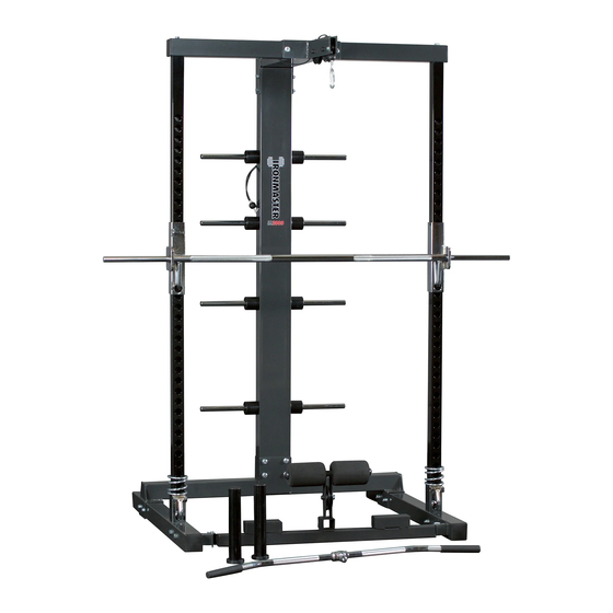
The IM2000 is a self-spotting weight training system. Built in upper and lower pulleys allow for
various cable exercises and the lifting bar can quickly and easily be locked out at many levels for
safety without the need for a spotter for lifting and pressing exercises. Secondary safety stops
add even more safety if needed. Bar and weight storage bars will hold Standard or Olympic style
weight plates. The IM2000 is designed to be used in conjunction with Ironmaster products and
attachments, but can accommodate other brands of plates, cable attachments and benches.
Weight rating is 1000 lbs/450 KGS for the frame and lifting bar. Cable System is rated for 350
lbs/159 KGS. Ironmaster recommends 2 people for assembly. Refer to this manual or the Iron-
master web site for further details regarding usage of the IM2000 and be sure to understand all
safety warning labels.
Advertisement

Related Manuals for Ironmaster IM2000


Summary of Contents for Ironmaster IM2000
- Page 1 Weight rating is 1000 lbs/450 KGS for the frame and lifting bar. Cable System is rated for 350 lbs/159 KGS. Ironmaster recommends 2 people for assembly. Refer to this manual or the Iron- master web site for further details regarding usage of the IM2000 and be sure to understand all safety warning labels.
- Page 2 Should any parts be broken or missing, please contact your near- est Ironmaster dealer or Ironmaster directly using the contact information provided in this manual. STEP ONE: Locate the following parts. L/R BASE LEGS/BASE CENTER/FOOTPLATE. You will also require 8x M12x100bolts/16x M12 Washers and 8x Nylock nuts.
-
Page 3: Slide Rail
STEP TWO: Locate the following parts. L/R SLIDE RAILS/Slide Rail Allen wrench (included)/2x 1/2”x25mm bolts and Spring Washers . CAUTION: Aligning the SLIDE RAILS and BASE FRAME assembly will require two people. With two people, tilt the BASE FRAME assembly and install the 1/2”x25mm bolts/washers from under- neath the BASE FRAME... -
Page 4: Safety Stop
STEP THREE: Locate the following parts. 2x SAFETY STOPS/2x SPRINGS and LIFTING BAR. No additional hardware is required for this portion of the assembly. Slide SAFETY STOP and SPRING over top of SLIDE RAIL as shown. Note SAFETY STOP hook faces down- ward and toward front so as to align with SLIDE RAIL holes. - Page 5 STEP FOUR: Locate the following parts. 1x REAR SPINE/1x TOP CENTER and 1x CROSS- MEMBER. You will also need 4x M12x 100mm bolts/8x M12 Washers and 4x Nylock Nuts for the SPINE and 2x M12x100mm Bolts/4x M12 Washers and 2x Nylock Nuts for the TOP CEN- TER/CROSSMEMBER assembly.
- Page 6 STEP FIVE: Attach the TOP CENTER/CROSSMEMBER assembly to the SPINE/SLIDE RAILS. Locate the following parts: 2x 1/2 inch x 100mmbolts (separately packaged in the bolt pack) and 2x M12x180mm bolts/2x M12 washers and 2x nylock nuts. TOP CENTER/CROSSMEMBER assembly Prepackaged 1/2 inch” x 100mm bolts for CROSSMEMBER into SLIDE RAIL Lift TOP CENTER assembly up onto the SLIDE RAILS and SPINE.
- Page 7 STEP FIVE: Locate the following parts and hardware. 4x PLATE HOLDERS/8x STAND OFF plas- tic spacers/1x J-HOOK /4x M10x 40mm bolts and 4x M10 washers. First, slide the 4x PLATE HOLDERS into the SPINE. Next, Install the M10x40mm bolts/M10 washers through the bottom three holes located in the rear of the SPINE and secure the PLATE HOLD- ERS into position.
- Page 8 STEP SIX: Locate the following parts and hardware. 1x UPPER PULLEY CABLE/2x M12x45mm bolts/M12 washers/2x nylock nuts and 2x PULLEYS Front PULLEY UPPER PULLEY CABLE UPPER CABLE J- hook Prior to installing the front PULLEY onto the TOP CENTER assembly, thread the UPPER PULLEY CABLE over the PULLEY and then install front PULLEY as shown left.
- Page 9 STEP SEVEN: Locate the following parts and hardware. 1x LOWER PULLEY BAR, 1x PULLEY, 1x M12x45mm bolt/1xM12 washer/1x nylock nut, 2x Plastic Caps/2x M8 x 25mm bolts/2x FOAM PADS/2x BALL PINS FOAM PAD PLASTIC END CAP M8 x 25mm bolt Washer (M8) M12x45mm bolt LOW PULLEY BAR...
- Page 10 To set up the LOW PULLEY BAR for use, first swing the Low Pul- ley bar into position and secure with BALL PIN. Next, attach LOW PULLEY CABLE to ball end of upper pulley by first threading eye- let end up through the LOW PULLEY BAR pulley and then secur- ing with Carabineer.
- Page 11 OPERATIONAL/SAFETY/MAINTAINANCE notes for IM2000 LIFTING BAR During normal use, the Normal use LIFTING BAR lock out pins Position will be in the downward po- sition with the safety bolt in Safety bolt the storage position above. Turn the bar slightly out-...
- Page 12 10 years for frame and structural components. Shipping costs are not included in the warranty and some items may need to be sent to Ironmaster for repair or replacement. I n stallation of any parts and labor involved is not included. The warranties described above shall be the sole and exclusive remedy available to the pu rchaser. Correction of...
Need help?
Do you have a question about the IM2000 and is the answer not in the manual?
Questions and answers