Table of Contents
Advertisement
Quick Links
"µboss" +0500152IE - rel. 1.1 - 20.10.2020
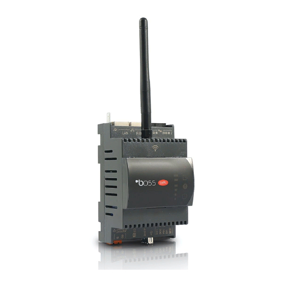
µboss:
Istruzioni di montaggio / Assembly procedure
DESCRIZIONE CONNETTORI / CONNECTOR'S DESCRIPTION
12
LAN
FIELD
11
14
4
2
1
3
Legenda / Key :
Descrizione
Description
Connettore per l'alimentazione [G(+), G0(-)] 24Vac/Vdc
1
Power supply connector [G(+), G0(-)] 24Vac/Vdc
2
LED power-on (verde) / LED power-on (green)
uSD-card reader per funzioni di backup/recovery
3
uSD-card reader for backup/recovery function
4
Led segnalazione Ethernet / Ethernet signal Led
5
Pulsante Reset e abilitazione IP temporaneo / Reset button and Enable temporary IP
Porta USB standard HOST, connettore tipo A, per upgrading FW e log files
6
downloading / Porta USB standard HOST, connettore tipo A, per upgrading FW
e log files downloading
Comando relay esterni e ingresso digitale a contatto pulito
7
external relay command and free contact digital input
8
Seriale RS485 Optoisolata / RS485 serial opto-isolated;
9
Seriale RS485 Non Optoisolata / RS485 serial not opto-isolated;
10
Ethernet FIELD / FIELD Ethernet ;
11
Ethernet LAN / LAN Ethernet ;
Faston collegamento a terra calza ethernet / Faston for shield ethernet port earth
12
connection
13
Connettore per antenna 2G/3G/4G / 2G/3G/4G Antenna connector (*)
14
Connettore per antenna Wi-Fi / Wi-Fi Antenna connector (*)
15
Sinottico LED / LED synoptic
16
Connettore SIM (*) / SIM connector (*)
(*) per i modelli che lo prevedono / depending on the model
SIGNIFICATO DEI LEDS / LEDS MEANINGS
E
Descrizione
Description
A
Modulo radio attivo / Radio module actived
B
Stato I/O / I/O Status
VERDE: ingresso digitale chiuso / GREEN: closed digital input
SPENTO: ingresso digitale aperto / OFF: opened digital input
C
ROSSO lampeggiante: Sistema in allarme / RED flashing: Alarm system
GIALLO: Sistema non inizializzato (manca il primo avvio) / YELLOW: System not initialized
(first boot missing)
Sistema acceso / System ON
D
E
Intensità segnale Radio 2G/3G/4G / Radio signal strength 2G/3G/4G
Primo LED giallo lampeggiante: relè 1 energizzato / First yellow LED flashing: relay 1
energized
Secondo LED giallo lampeggiante: relè 2 energizzato / Second yellow LED flashing: relay
2 energized
DIMENSIONI / DIMENSIONS
70
Montaggio DIN: agganciabile su guida DIN secondo DIN 43880 CEI EN 50022
DIN mounting: fitted on DIN rail in accordance with DIN 43880 and IEC EN 50022;
ATTENZIONE
Quest'apparecchiatura deve essere installata esclusivamente da personale
di servizio con adeguato addestramento tecnico ed esperienza per essere
consapevole dei pericoli a cui può essere esposto in caso di configurazione
erronea (installatori abilitati).
NOTE GENERALI
Prima di passare a qualsiasi operazione si raccomanda di controllare che nella scatola
di µboss siano presenti:
1. il dispositivo stesso;
2. nelle versioni wireless una antenna (tipo Wi-Fi o 2G/4G); Per i modelli con due radio ci
devono essere due antenne;
3. documentazione tecnica;
4. kit morsetti estraibili e due resistori da 120Ω per terminazione di linea seriale.
Evitare il montaggio del prodotto in ambienti che presentino le seguenti
8
caratteristiche:
2
9
•
umidità relativa maggiore di quanto indicato nelle specifiche tecniche;
•
10
forti vibrazioni o urti;
•
esposizione ad atmosfere aggressive ed inquinanti (es.: gas solforici e ammoniacali,
13
nebbie saline, fumi) con conseguente corrosione e/o ossidazione;
•
elevate interferenze magnetiche e/o radiofrequenze (evitare quindi l'installazione
delle macchine vicino ad antenne trasmittenti);
•
esposizione all'irraggiamento solare diretto e agli agenti atmosferici in genere;
•
15
ampie e rapide fluttuazioni della temperatura ambiente;
•
ambienti ove sono presenti esplosivi o miscele di gas infiammabili.
16
Avvertenze per l'installazione per i modelli con radio
•
Prima di installare il prodotto verificare che la zona sia coperta adeguatamente dal
segnale 2G/3G/4G, se il modello da utilizzare prevede tale connettività radio;
•
posizionare l'antenna al di fuori di carpenterie metalliche.
CARATTERISTICHE TECNICHE
Alimentazione
Potenza ingresso
I/O
Cond. di Funzionamento
6
Cond. di Stoccaggio
2 uscite digitali
7
1 ingresso
5
Porte seriali
Batteria interna
Requisiti di certificazione:
RED:
- WIFI
- 2G/3G/4G
FCC:
- WIFI+2G/3G/4G
Safety:
ANATEL
Dimensioni
Grado di inquinamento
Grado di protezione
Materiale del contenitore
Non aprire il dispositivo quando alimentato.
Alimentazione
•
L'alimentazione del prodotto si deve effettuare unicamente tra G e G0;
•
lunghezza massima=5 m;
•
se alimentato in alternata utilizzare un trasformatore dedicato di sicurezza di classe 2
da 24Vac, 20...30VA, protetto contro il cortocircuito e il sovraccarico, senza collegare
il secondario a terra;
•
se alimentato in continua usare l'alimentatore PGTA00TRX0, 100/230Vac-24Vdc (10W
±2% 1 modulo DIN, Temperatura minima = -25°C). Collegare il polo positivo a G e
il negativo a G0.
Ingressi e uscite digitali
•
Uscite digitali open-collector pre-configurate in modalità "safe-mode": per notificare
una condizione di allarme l'uscita viene de-energizzata. Collegare solo il modulo relè
esterno BMESTRLA00 con cavi di lunghezza inferiore a 1m;
•
ingresso digitale contatto pulito, distanza inferiore ai 10m.
ATTENZIONE: utilizzare cavi separati per ingresso digitale, comandi relè,
connessioni seriali e alimentazione.
LINEE DI COMUNICAZIONE
A
Linee di comunicazione RS485
La lunghezza massima non deve superare i 1000m, tramite cavo schermato AWG24
B
per linee max 100m, AWG22 per linee max 500m AWG20 per linee max 1000m, con
connessione dello schermo a terra e non a GND.
C
Le resistenze di terminazione 120 Ω, 1/4W sul primo e sull'ultimo dispositivo della
rete vanno messe se la lunghezza della stessa supera i 100 m. Resistenze incluse nel
prodotto da collegare tra i morsetti seriale + e -
D
•
rispettare la polarità (-,+,GND);
•
non realizzare biforcazioni della linea o collegamenti a stella;
•
evitare di posizionare la linea in prossimità delle linee di potenza;
Per migliorare l'immunità del controllo ai disturbi elettromagnetici, il cavo di
collegamento delle seriali deve essere a coppie ritorte (twisted pair), schermato,
bipolare o tripolare in dipendenza dall'isolamento della seriale.
Vale la seguente regola:
•
se la porta seriale è optoisolata (funzionalmente) rispetto all'alimentazione, occorre
un terzo filo di collegamento nel cavo seriale per dare un riferimento comune ai
controlli.
•
se la porta seriale non è optoisolata e il riferimento comune è già presente, il terzo
filo non è usato.
Linee Ethernet RJ45
Utilizzare cavo schermato 100 m Cat.5e SFTP. Per collegare lo schermo
del cavo ethernet a terra funzionale, utilizzare un Faston femmina da
6,3mm come indicato in figura.
Il prodotto è di classe II, ma è presente il faston per la messa a terra funzionale della
schermatura del cavo Ethernet. Il collegamento potrebbe essere verso una terra di
protezione o, eventualmente una terra funzionale separata da tensioni pericolose
fornite da altre alimentazioni esterne.
INSTALLAZIONE
Per tutelare la sicurezza degli operatori e la salvaguardia del dispositivo, prima di
effettuare qualsiasi intervento togliere l'alimentazione. Il prodotto va installato
all'interno di un quadro elettrico, che se di materiale plastico deve avere grado di
infiammabilità 5VA.
Collegare solo le antenne indoor presenti nella confezione.
Se c'è la necessità di installare il prodotto in un quadro metallico
è opportuno remotare le antenne. Il quadro elettrico metallico
deve essere connesso a terra. A tale scopo utilizzare la prolunga
BMBSTEWA00 (Wi-Fi) e/o BMBSTEGA00 (2G/3G/4G). La lunghezza
massima della prolunga è di 3 m sia per il Wi-Fi sia per 2G/3G/4G.
Non esporre l'antenna agli agenti atmosferici (pioggia, HV,
fulmini, ecc. ) senza adeguata protezione.
60
Attenz.: non invertire le antenne Wi-Fi con 2G/3G/4G.
Nel caso di modelli con entrambi i moduli Wi-Fi e 4G è necessario
remotare l'antenna 4G per non avere interferenza con il Wi-Fi
(vedi figura).
tra G e G0: 24 Vac +10%/-15% 50/60 Hz , 24 Vdc, ±5%
Max 9W
-40T60 °C, 90% U.R. non-condensante.
-40T70 °C, 90% U.R. non-condensante
Open-collector, per ogni uscita max carico 20mA
contatto pulito: max 24Vdc, max 5mA
1 RS485 Master optoisolata - 1 RS485 Master non optois.
Batteria Lithium bottone, BR2032, 3 Vdc, NON ricaricabile.
EN 301 489-1
EN 301 489-17 Ver. 3.1.1; EN 300 328 Ver. 2.1.1
EN 301 489-52 Ver. 1.1.0; EN 301 511 Ver. 12.5.1;
EN 301 908-1 Ver. 11.1.1
FCC Part 15 Subpart B, ICES003
FCC Part 15.31 (k); ANSI C95.1. MPE; RSS-102. MPE
60950; 62368
Questa apparecchiatura non ha diritto alla protezione da
interferenze dannose e non deve causare interferenze in
sistemi debitamente autorizzati
modulo 4 DIN = 70x110x60 mm
2 secondo EN60950-1 / EN62368-1
IP10
tecnopolimero
Shielded
cable
2/3m
WARNING
This appliance must only be installed by service personnel with suitable
technical training and experience and who are aware of the dangers they may
be exposed to in the event of incorrect configuration (qualified installers).
GENERAL NOTE
Before performing any operations, check that the µboss contains:
1. the device itself;
2. for wireless version: an antenna ( Wi-Fi or 2G/4G type). For models with two radios there
must be two antennas.
3. technical documents;
4. terminals kit and two resistors 120Ω for the end of the serial line.
Do not install products in environments with the following characteristics:
•
relative humidity greater than the value specified in the technical specifications;
•
strong vibrations or knocks;
•
exposure to aggressive and polluting atmospheres (e.g.: sulphur and ammonia
fumes, saline mist, smoke) so as to avoid corrosion and/or oxidation;
•
strong magnetic and/or radio frequency interference (therefore avoid installing the
units near transmitting antennae);
•
exposure to direct sunlight and to the elements in general;
•
large and rapid fluctuations in the room temperature;
•
environments where explosives or mixes of flammable gases are present.
Installation warnings for Radio models
•
Before installing the product make sure the area is sufficiently covered by a 2G/3G/4G
signal, if the model to be used includes radio connectivity;
•
locate the antenna outside metal hardware.
TECHNICAL SPECIFICATIONS
Power supply
from G to G0: 24 Vac +10%/-15% 50/60 Hz, 24 Vdc, ±5%
Input power
9W Max
Operating conditions
-40T60 °C, 90% U.R. non-condensing
Storage conditions
-40T70 °C, 90% U.R. non-condensing
2 digital outputs
Open-collector, on each output 20mA max. load
1 input
free contact: 24Vdc max, 5mA max
Serial Ports
1 RS485 Master optoisolated- 1 RS485 Master non optoisolated
Battery (internal)
Lithium "button" type, BR2032, 3 Vdc, NON rechargeable
Certification requirements
RED:
EN 301 489-1
EN 301 489-17 Ver. 3.1.1; EN 300 328 Ver. 2.1.1
- WIFI
EN 301 489-52 Ver. 1.1.0; EN 301 511 Ver. 12.5.1;
- 2G/3G/4G
EN 301 908-1 Ver. 11.1.1
FCC:
FCC Part 15 Subpart B, ICES003
FCC Part 15.31 (k); ANSI C95.1. MPE; RSS-102. MPE
- WIFI+2G/3G/4G
Safety:
60950; 62368
ANATEL
This equipment is not entitled to protection against harmful
interference and may not cause interference in duly authorized
systems.
Dimensions
4 DIN module = 70x110x60 mm
Pollution degree
2 according to EN60950-1 / EN62368-1
Index of protection
IP10
Case material
tecnopolymer
Do not open the device when powered.
Power supply
•
Power supply to the product must only be connected between G and G0
•
Maximum length =5 m.
•
If AC powered, use a dedicated safety transformer rated in Class 2 24Vac, 20...30VA,
protected against short-circuits and overload
,
without secondary must be
earthed connected
.
•
If direct current powered use PGTA00TRX0 power supply, 100/230Vac-24Vdc (10W
±2% 1 DIN-module, Minimum Temperature = -25°C). Connect the positive pole to
G and negative pole to G0.
Digital inputs and digital outputs
•
Open-collector
pre-configured digital input "safe-mode": to notify an alarm
condition the output is de-energized. Connect only the BMESTRLA00 external relay
module with cables lenght less 1m;
•
free contact digital input, distance less 10m.
CAUTION: use separate cables for serial connections and power supply.
COMMUNICATION LINES
RS485 communication lines
The maximum length must not be over 1000m, via AWG24 shielded cable for lines max
100m, AWG22 for lines max 500m, AWG20 for lines max 1000m lenght, with screen
connection to earth and not to GND. The 120Ω terminal resistors, 1/4W into the first
and the last devices of the network, must be connected even if the lenght exceeds 100
meters. The resistors, included in the product, are to be connected between the serial
+ and - terminals:
•
observe the polarity (+.-,GND);
•
do not make branches in the line or star connections;
•
avoid laying the line near power cables.
To improve immunity of the controller to electromagnetic disturbance, the serial
connection cable must be twisted pair shielded, twisted two- or three-wire depending
on the insulation of the serial connection.
The following rule applies:
•
if the serial port is insulated (functionally) from the power supply, a third wire is
required in the serial cable to act as a common reference for the controllers;
•
if the serial port is not optically-isolated and the common reference is already
present, the third wire is not needed.
RJ45 Ethernet Linee
Use shielded cables 100 m Cat.5e SFTP. To connect earth the screen
ethernet cable (functional connection), use a female Faston 6,3mm, as
indicated inthe figure.
The product is class II classified, but there is a faston for the earth connection (functional)
shiel cable. The connection could be directed to earth (protection) or, earth (functional)
separated by dangerous voltages from to other external power supplies.
MOUNTING
To safeguard operators and the boards, disconnect power before performing any
operations. The product must be installed inside an electrical panel if it is made of
plastic material use one with flammability rating of 5VA.
Connect only the indoor antennas in the package.
If necessary to install the product in a metal electrical panel, it
is recommended to remote the antennas. The metallic electrical
panel must be earthed. Use the extension BMBSTEWA00 (Wi-
Fi) and/or BMBSTEGA00 (2G/3G/4G). The extention maximum
length is 3 m, for Wi-Fi and 2G/3G/4G.
Not exposure the antenna to the atmospheric agent (rain, UV
lightning, etc.) without a proper protection.
Attention.: do not invert the antennas Wi-Fi with 2G/3G/4G.
If using models with both Wi-Fi and 4G modules, it is necessary
to remotely control the 4G antenna to avoid interference with
Wi-Fi (see figure).
Shielded
cable
2/3m
Advertisement
Table of Contents

Subscribe to Our Youtube Channel
Related Manuals for Carel boss

Summary of Contents for Carel boss
- Page 1 (installatori abilitati). NOTE GENERALI GENERAL NOTE Prima di passare a qualsiasi operazione si raccomanda di controllare che nella scatola Before performing any operations, check that the µboss contains: di µboss siano presenti: 1. the device itself; 1. il dispositivo stesso;...
- Page 2 CAREL editate nel sito www.carel.com e/o da specifici accordi con i clienti. To assign a temporary IP address to the µboss LAN port for access when the actual IP is Per assegnare un IP fisso temporaneo alla porta LAN di µboss in modo da potervi not known, proceed as follows: •...
Need help?
Do you have a question about the boss and is the answer not in the manual?
Questions and answers