Table of Contents
Advertisement
Quick Links
www.ti.com
User's Guide
LMG342XEVM-04X User Guide
The LMG342XEVM-04X features two LMG342XR0X0 600-V GaN FETs with an integrated driver and protection
in a half-bridge configuration with all the required bias circuit and logic/power level shifting. Essential power
stage and gate-driving, high-frequency current loops are fully enclosed on the board to minimize power loop
parasitic inductance for reducing voltage overshoots and improving performance. The LMG342XEVM-04X is
configured for a socket style external connection for easy interface with external power stages to run the
LMG342XR0X0 in various applications. Refer to the LMG342XR0X0 data sheet before using this EVM.
1 General TI High Voltage Evaluation User Safety Guidelines .............................................................................................
1.1 Safety and Precautions......................................................................................................................................................
2
Introduction.............................................................................................................................................................................5
2.1 LMG342XEVM-04X Daughter Card...................................................................................................................................
Boards....................................................................................................................................................................9
Applications............................................................................................................................................................9
2.4 Features.............................................................................................................................................................................
3 LMG342XEVM-04X Schematic.............................................................................................................................................
Schematic......................................................................................................................................................12
5 Recommended Footprint.....................................................................................................................................................
6 Test Equipment.....................................................................................................................................................................
7.1
Setup................................................................................................................................................................................16
7.2 Start-Up and Operating Procedure..................................................................................................................................
Results......................................................................................................................................................................18
Procedure........................................................................................................................................................19
7.5 Additional Operating Notes..............................................................................................................................................
8 Test Procedure When Paired With LMG34XX-BB-EVM.....................................................................................................
8.1
Setup................................................................................................................................................................................20
8.2 Start-Up and Operating Procedure..................................................................................................................................
Procedure........................................................................................................................................................23
8.4 Additional Operation Notes..............................................................................................................................................
9 Bill of Materials.....................................................................................................................................................................
10 Revision History.................................................................................................................................................................
Figure 2-1. LMG342XEVM-04X Block Diagram..........................................................................................................................
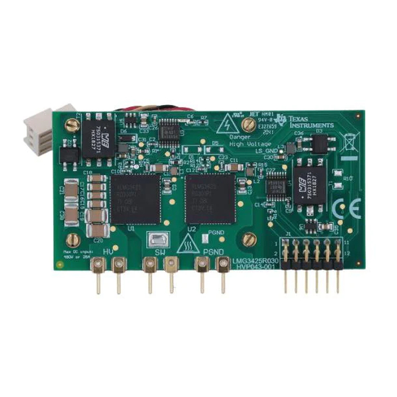
Figure 2-2. Front Side View of the EVM......................................................................................................................................
Figure 3-1. LMG342XEVM-04X Schematic...............................................................................................................................
Figure 4-1. LMG342X-BB-EVM Schematic...............................................................................................................................
Figure 4-2. LMG34XX-BB-EVM Schematic...............................................................................................................................
Figure 5-1. Recommended Footprint for LMG342XEVM-04X ..................................................................................................
Figure 7-1. LMG342X-BB-EVM Motherboard With LMG342XEVM-04X ..................................................................................
Figure 7-4. 85 V/ns at 400 V/20 A.............................................................................................................................................
Figure 7-5. 100 V/ns at 400 V/20 A...........................................................................................................................................
Figure 7-6. 30 V/ns at 400 V/20 A.............................................................................................................................................
Figure 7-7. 150 V/ns at 400 V/5 A.............................................................................................................................................
SNOU176B - OCTOBER 2020 - REVISED MARCH 2022
Submit Document Feedback
ABSTRACT
Table of Contents
LMG342X-BB-EVM......................................................................................................16
List of Figures
EVM.......................................................................................................................................8
LMG342X-BB-EVM....................................................................................................17
Copyright © 2022 Texas Instruments Incorporated
Table of Contents
Connection..........................17
LMG342XEVM-04X User Guide
3
4
5
9
10
14
15
17
19
20
22
23
24
27
6
8
10
12
13
14
16
18
18
19
19
1
Advertisement
Table of Contents

Subscribe to Our Youtube Channel
Related Manuals for Texas Instruments LMG342XEVM-04X


Summary of Contents for Texas Instruments LMG342XEVM-04X
-
Page 1: Table Of Contents
LMG342XEVM-04X User Guide ABSTRACT The LMG342XEVM-04X features two LMG342XR0X0 600-V GaN FETs with an integrated driver and protection in a half-bridge configuration with all the required bias circuit and logic/power level shifting. Essential power stage and gate-driving, high-frequency current loops are fully enclosed on the board to minimize power loop parasitic inductance for reducing voltage overshoots and improving performance. - Page 2 Table 2-3. Power Pin Function Description..........................6 Table 8-1. Test Point Functional Description..........................22 Table 8-2. List of Terminals................................ Table 9-1. Bill of Materials for LMG342XEVM-04X ........................24 Table 9-2. Bill of Materials for LMG342X-BB-EVM........................Trademarks All trademarks are the property of their respective owners.
-
Page 3: General Ti High Voltage Evaluation User Safety Guidelines
• Limitation for Safe Use: – EVMs are not to be used as all or part of a production unit. SNOU176B – OCTOBER 2020 – REVISED MARCH 2022 LMG342XEVM-04X User Guide Submit Document Feedback Copyright © 2022 Texas Instruments Incorporated... -
Page 4: Safety And Precautions
For safety, use of isolated test equipment with overvoltage and overcurrent protection is highly recommended. LMG342XEVM-04X User Guide SNOU176B – OCTOBER 2020 – REVISED MARCH 2022 Submit Document Feedback Copyright © 2022 Texas Instruments Incorporated... -
Page 5: Introduction
Introduction 2 Introduction The LMG342XEVM-04X operates as a half-bridge daughter card that can be either part of a larger custom designed system or paired with the mother board. TI provides two mother boards (LMG342X-BB-EVM and LMG34XX-BB-EVM) to interface with LMG342XEVM-04X. LMG342X-BB-EVM can support up to 4-kW, and LMG34XX-BB-EVM can provide up to 1.7-kW. -
Page 6: Figure 2-1. Lmg342Xevm-04X Block Diagram
EVM. 2.1.1 FAULT and OC The FAULT and OC pins of the LMG342XEVM-04X are active low when an undervoltage lockout occurs on an auxiliary voltage rail, when an overtemperature event occurs, or when an overcurrent/short-circuit event occurs on the LMG342XR0X0. - Page 7 LMG342XEVM-04X. 2.1.3 Bootstrap Mode The LMG342XEVM-04X card can be modified to operate in bootstrap mode, where the 12-V bias voltage is used to power both LMG342XR0X0 devices. This mode can be achieved by the following modifications to the EVM: 1. Remove R1.
-
Page 8: Figure 2-2. Front Side View Of The Evm
Introduction www.ti.com Figure 2-2. Front Side View of the EVM Figure 2-3. Back Side View of the EVM LMG342XEVM-04X User Guide SNOU176B – OCTOBER 2020 – REVISED MARCH 2022 Submit Document Feedback Copyright © 2022 Texas Instruments Incorporated... -
Page 9: Mother Boards
There is an option to disable the PWM input to the daughter card in the event of a fault signal from the LMG342XEVM-04X. When the FAULT Protect jumper is placed in the EN mode, PWM is disabled when either LMG342XR0X0 has an active fault. This disable is not latching, so PWM immediately resumes when the fault clears. -
Page 10: Lmg342Xevm-04X Schematic
4.7uF 4.7uF 4.7uF SN6505BDBVR SN6505BDBVR ISO_RET_H_B ISO_RET_L_B Max. 1A current on the FET PGND AGND AGND LMG342XEVM-04X User Guide SNOU176B – OCTOBER 2020 – REVISED MARCH 2022 Submit Document Feedback Figure 3-1. LMG342XEVM-04X Schematic Copyright © 2022 Texas Instruments Incorporated... - Page 11 When the high-side power supply is fully charged, the low-side device can shift back to a higher slew rate in normal operation. This is realized using Q1 and R18. R14 of 100 kΩ is used to control the slew rate. SNOU176B – OCTOBER 2020 – REVISED MARCH 2022 LMG342XEVM-04X User Guide Submit Document Feedback Copyright © 2022 Texas Instruments Incorporated...
-
Page 12: Mother Board Schematic
0.1uF 0.1uF PGND5 PGND PGND AGND AGND AGND AGND1 PGND4 PGND 3267 PGND1 PGND PGND2 PGND Figure 4-1. LMG342X-BB-EVM Schematic LMG342XEVM-04X User Guide SNOU176B – OCTOBER 2020 – REVISED MARCH 2022 Submit Document Feedback Copyright © 2022 Texas Instruments Incorporated... -
Page 13: Figure 4-2. Lmg34Xx-Bb-Evm Schematic
282834-2 AGND1 AGND PGND PGND Green PGND2 AGND ACMGND AGND2 Copyright © 2016, Texas Instruments Incorporated Figure 4-2. LMG34XX-BB-EVM Schematic SNOU176B – OCTOBER 2020 – REVISED MARCH 2022 LMG342XEVM-04X User Guide Submit Document Feedback Copyright © 2022 Texas Instruments Incorporated... -
Page 14: Recommended Footprint
5 Recommended Footprint When the EVM daughter card is used in a custom design system, the recommended footprint to interface with the LMG342XEVM-04X daughter card is shown below. Figure 5-1. Recommended Footprint for LMG342XEVM-04X LMG342XEVM-04X User Guide SNOU176B – OCTOBER 2020 – REVISED MARCH 2022 Submit Document Feedback Copyright ©... -
Page 15: Test Equipment
50 kHz to 200 kHz in hard-switching converters. Note TI provides a custom interposer board that must be used when the LMG342XEVM-04X is paried with the LMG34XX-BB-EVM. The interposer board is not needed with LMG342x-BB-EVM. Oscilloscope: Capable of at least 200 MHz operation. A 1 GHz or greater oscilloscope and probes with short ground springs are required for accurate measurements. -
Page 16: Test Procedure When Paired With Lmg342X-Bb-Evm
The inductor on LMG342X-BB-EVM is capable of around 3-kW operation. For higher power levels, use an external inductor. TI recommends the following procedure to set up the LMG342X-BB-EVM with the LMG342XEVM-04X: 1. Connect the LMG342XEVM-04X to LMG342X-BB-EVM as shown in Figure 7-1. -
Page 17: Start-Up And Operating Procedure
(up to 480V). As the voltage is ramping up, the HV LED will turn on and become brighter. Figure 7-3. Switch-Node Voltage Measurement with High-Bandwidth Probe and Pigtail Ground Connection SNOU176B – OCTOBER 2020 – REVISED MARCH 2022 LMG342XEVM-04X User Guide Submit Document Feedback Copyright © 2022 Texas Instruments Incorporated... -
Page 18: Test Results
Figure 7-4. 85 V/ns at 400 V/20 A Load Current(10A/div) Slew rate: 100V/ns Switch Node Voltage(100V/div) Figure 7-5. 100 V/ns at 400 V/20 A LMG342XEVM-04X User Guide SNOU176B – OCTOBER 2020 – REVISED MARCH 2022 Submit Document Feedback Copyright © 2022 Texas Instruments Incorporated... -
Page 19: Shutdown Procedure
Fault protection on the LMG342X-BB-EVM is not latching, therefore PWM will resume if a fault clears and the LMG342X-BB- EVM is still operational. SNOU176B – OCTOBER 2020 – REVISED MARCH 2022 LMG342XEVM-04X User Guide Submit Document Feedback Copyright © 2022 Texas Instruments Incorporated... -
Page 20: Test Procedure When Paired With Lmg34Xx-Bb-Evm
LMG342XEVM-04X connected to the LMG34XX-BB-EVM. Note TI provides a custom interposer board that must be used when the LMG342XEVM-04X is paired with the LMG34XX-BB-EVM. The interposer board is not needed with LMG342x-BB-EVM. Figure 8-1. LMG342XEVM-04X Connected to the LMG34XX-BB-EVM LMG342XEVM-04X User Guide SNOU176B –... -
Page 21: Figure 8-2. Recommended Connection Points
Figure 8-2. Recommended Connection Points PCB Notes: • A: Probe points for gate drive logic • B: 100-mil header for PWM input, PWM signals to LMG342XEVM-04X and FAULT output • C: BNC connector for PWM input • D: 12-V bias supply input •... -
Page 22: Start-Up And Operating Procedure
Connector to interface LMG342XEVM-04X board 8.2 Start-Up and Operating Procedure The following procedure is recommended to enable the LMG342XEVM-04X with the LMG342XEVM-04X: 1. Power up the 12-V bias supply. Ensure the top right green “Aux Enable” LED is illuminated. 2. Enable PWM on the function generator. -
Page 23: Shutdown Procedure
Fault protection on the LMG34XX-BB-EVM is not latching, therefore PWM will resume if a fault clears and the LMG34XX-BB- EVM is still operational. SNOU176B – OCTOBER 2020 – REVISED MARCH 2022 LMG342XEVM-04X User Guide Submit Document Feedback Copyright © 2022 Texas Instruments Incorporated... -
Page 24: Bill Of Materials
Bill of Materials www.ti.com 9 Bill of Materials Table 9-1. Bill of Materials for LMG342XEVM-04X DESIGNATOR DESCRIPTION PART NUMBER C1, C11 CAP, CERM, 10 µF, 25 V,+/- 10%, X7R, AEC-Q200 Grade 1, 1206 TMK316AB7106KLHT C2, C12 CAP, CERM, 0.22 µF, 16 V,+/- 10%, X7R, AEC-Q200 Grade 1, 0402... -
Page 25: Table 9-2. Bill Of Materials For Lmg342X-Bb-Evm
Bill of Materials Table 9-1. Bill of Materials for LMG342XEVM-04X (continued) DESIGNATOR DESCRIPTION PART NUMBER RES, 2.05, 1%, 0.25 W, AEC-Q200 Grade 0, 1206 CRCW12062R05FKEA R3, R12, R18 RES, 0, 5%, 0.1 W, AEC-Q200 Grade 0, 0402 ERJ-2GE0R00X R5, R14, R17 RES, 20 k, 5%, 0.1 W, AEC-Q200 Grade 0, 0402... - Page 26 SN74LVC3G14DCUTG4 1A SIMPLE SWITCHER® Power Module with 20V Maximum Input LMZ12001EXTTZ/NOPB Voltage for Military and Rugged Applications, 7 pin TO-PMOD LMG342XEVM-04X User Guide SNOU176B – OCTOBER 2020 – REVISED MARCH 2022 Submit Document Feedback Copyright © 2022 Texas Instruments Incorporated...
-
Page 27: Revision History
Added the Test Results section........................• Revised the Test Procedure When Paired With LMG34XX-BB-EVM section...........20 • Updated Table 9-1 ............................SNOU176B – OCTOBER 2020 – REVISED MARCH 2022 LMG342XEVM-04X User Guide Submit Document Feedback Copyright © 2022 Texas Instruments Incorporated... - Page 28 TI products. TI’s provision of these resources does not expand or otherwise alter TI’s applicable warranties or warranty disclaimers for TI products. TI objects to and rejects any additional or different terms you may have proposed. IMPORTANT NOTICE Mailing Address: Texas Instruments, Post Office Box 655303, Dallas, Texas 75265 Copyright © 2022, Texas Instruments Incorporated...
Need help?
Do you have a question about the LMG342XEVM-04X and is the answer not in the manual?
Questions and answers