Advertisement
Advertisement

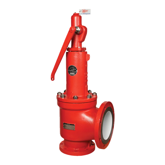
Summary of Contents for Farris Engineering Curtiss-Wright 2600 Series
- Page 1 Technical Manual 1098T R1 Pressure Relief Valve Maintenance Manual...
-
Page 2: Table Of Contents
Table of Contents Introduction & Safety Tips ................1 Threaded Valve Cutaway Drawings ............5 2600 Series Disassembly Instructions ............2 Test Lever Assemblies ................6 2600 Series Cutaway Drawing ..............3 Cleaning & Lapping Procedures ..............7 Threaded Valve Disassembly Instructions ..........4 Testing Procedures ................8-9 1. -
Page 3: 2600 Series Disassembly Instructions
4. 2600, 2600L, & 2600S 14. On all but the “D” and “E” orifice bellows valves, the disc holder and stem retainer are held together by the disc holder lock screw. Insert Series Valves the proper size allen wrench into the opening in the disc holder. Turn the allen screw into the stem retainer clockwise. -
Page 4: 2600 Series Cutaway Drawing
Figure 1: 2600, 2600S & 2600L Details - Optional O Ring Seats L through T orifice D through K orifice Figure 1: 2600, 2600L & 2600S Series Parts List Body Lock Screw (B.D.R.) Bonnet Gasket Bonnet or Yoke Lock Screw Stud Lock Screw Gasket Stem Retainer Hex Nut (B.D.R.L.S.) -
Page 5: Threaded Valve Disassembly Instructions
5. Threaded Valves The disassembly of all valves follows the same basic procedure. This 13. 2700 Series Only: Remove the body from the vise and invert assembly, section pertains to 2700, 2850, 2856, 1890, and 1896M Series Valves. carefully removing the guide which contains the disc and disc holder. Please refer to the appropriate drawings. -
Page 6: Threaded Valve Cutaway Drawings
Series 2700 Series 2850 & 2856 Figure 3 Figure 3: Parts List - Threaded Valves Body Spring Adjusting Screw Grooved Pin Bonnet Jam Nut (Spr. Adj. Scr.) Lift Stop Ring Blow Down Ring Retaining Ring, Stem Shoulder Disc Lock Screw (B.D.R.) Cap Gasket Disc Holder Spring... -
Page 7: Test Lever Assemblies
6. Lever Assemblies - Figure 4 A. 2600 & 2600S Series B. Threaded Valves Open Lever: Single Acting Open Lever 150# & 300#LW Flanges Threaded Valves All Sizes Except 8 x 10 Open Lever: Double Acting Packed Lever 1 x 2 thru 6 x 10 300# thru 2500# Flanges Threaded Valves Sizes 8 x 10, All Types Parts List - Lever Assemblies... -
Page 8: Cleaning & Lapping Procedures
7. Cleaning & Lapping Each part should receive a visual examination for signs of wear and 4. Lap to a mirror finish. When done, make sure all compound is corrosion. Parts that show signs of excessive corrosion or wear should be completely removed from the parts using a suitable solvent. -
Page 9: Testing Procedures
8. Testing Procedures Testing consists of adjusting the valve set pressure, performing a seat 6. Lock the jam nut in place and pop the valve once more to ensure the leakage test, and a back pressure test. The set pressure test is always set pressure adjustment was not disturbed. - Page 10 8. Testing Procedures (continued) Seat Leakage Test: 4. Steam: Test pressure per paragraph 2 shall be applied for 3 minutes before the seat tightness test. The valve should be observed for leakage 1. Next perform a seat leakage test. With the valve mounted on the test for at least one minute.
- Page 12 Nothing contained herein is to be construed as a warranty or guarantee, expressed or implied, regarding the performance, merchantability, fitness or any other matter with respect to the products, nor as a recommendation to use any product or process in conflict with any patent. Farris Engineering, division of Curtiss-Wright Flow Control Corporation, reserves the right, without notice, to alter or improve the designs or specifications of the products described herein.


Need help?
Do you have a question about the Curtiss-Wright 2600 Series and is the answer not in the manual?
Questions and answers