
Related Manuals for Aimco AcraDyne ABETP Cordless XT Series


Summary of Contents for Aimco AcraDyne ABETP Cordless XT Series
- Page 1 ABETP Cordless XT Series Operations Manual 10000 SE Pine St., Portland OR 97216 • 800-852-1368 • Fax 800-582-9015 www.aimco-global.com...
-
Page 2: Table Of Contents
TABLE OF CONTENTS 1. General Safety Instructions ..3 7.5.8 DateTime ....31 7.5.9 Battery Selection ..32 1.1 Safety Instructions . -
Page 3: General Safety Instructions
1. General Safety Instructions 1.1 Safety Instructions Important Please do not operate this tool before reading this manual. If the tool is faulty or damaged, please do not attempt to repair it. Contact your local distributor immediately 1.1.1 General Safety WARNING: Please read all the instructions. -
Page 4: Electrical Safety
1.1.3 Electrical Safety 1. The connector of the battery must match identically to the connector built within the tool handle. Under no circumstances should the connections between battery and tool be modified. Battery should also securely firmly connect to the tool with its designed locking mechanism. -
Page 5: Tool Safety
4. Store the battery away from metal products, such as paper clips, coins, keys, screws, or other small metal objects, which may connect the battery port and cause fire due to short circuit of the battery. WARNING: In extreme cases, the battery may leak liquid. Avoid contact with liquid. -
Page 6: Abetp Operation Statement
2. ABETP Operation Statement 1. The ABETP torque wrench is used for final tightening applications. The operator shall formulate inspection and operation regulations to ensure the tightening quality through reasonable use specifications. If the operator fails to use the equipment through reasonable use specifications, resulting in abnormal working results of the equipment, the equipment shall not bear relevant responsibilities. -
Page 7: Service
4. Maintain battery tools regularly. When there is a problem with the electric torque wrench, examine the tool. If the tool is found to be damaged, contact the distributor to solve the problem. Many accidents are caused by the lack of proper tool maintenance. 5. -
Page 8: Tool Features
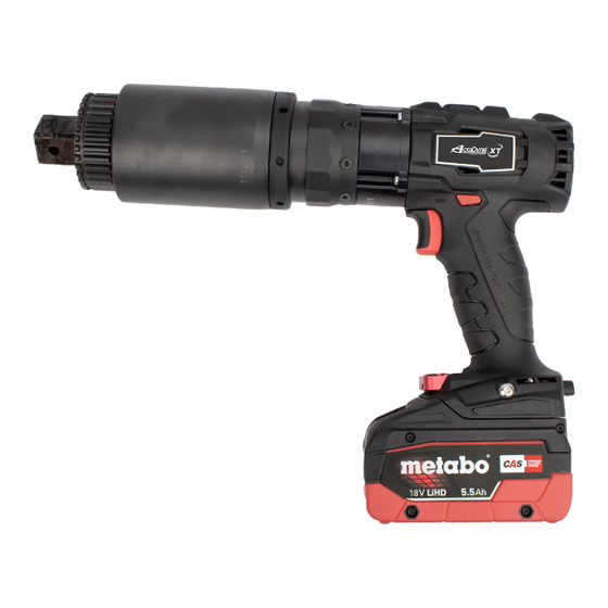
4. Tool Features 4.1 Tool Description ABETP series tools deliver high amounts of torque with transducer control and the ability to either monitor and/or control angle to the fastener. Tools consist of: • Driving Motor with Integrated Gearbox and Torque Sensor •... -
Page 9: Workflow
4.3 Workflow 4.4 Mechanical Operation Forward / Reverse / Lock Switch Controls the rotational direction of the motor. Switch can be pressed from both sides. When pressed in from the left side, the tool will rotate counterclockwise. When pressed in from the right side, Trigger the tool will rotate clockwise. -
Page 10: Operational Interface
5. Operational Interface 5.1 Main Interface Tool status Detected motor battery temperature Battery level indicator Control strategy Direction of operation Target value Unit of measure 5.1.1 Key Description Key No. Function Select the previous mode or function menu, or increase the value during setting Accept the selected mode or function, or enter the main menu in the main interface Select next mode or function menu, or reduce the value during setting 5.1.2 Icon Descriptions... -
Page 11: Menu Selection
5.2 Menu Selection Press key from the main screen to enter the operation selection interface. Seven operations are available in the following order. The function of each operation will be detailed in “7. Tool Settings” on p. 13. Icon Function Select operation mode Set presets prior to operation... -
Page 12: Menu Relationships
6. Menu Relationships... -
Page 13: Tool Settings
7. Tool Settings 7.1 Mode The ABETP torque wrench has three operation modes: Torque mode, Preset mode (Torque + Angle), and Angle mode. Mode Function Torque Directly set the set torque value for operation Preset Select preset working torque + angle values for operation Angle Directly set the angle value for operation To check the current Mode setting:... -
Page 14: Torque Mode
7.1.1 Torque Mode Torque Mode allows you to directly set the torque value for operation. 1. To set the tool to Torque operation mode, from the main tool screen, press key to enter the Mode screen. Press key again to enter the ... -
Page 15: Preset Mode (Torque + Angle)
7.1.2 Preset Mode (Torque + Angle) mode enables you to quickly set the working torque plus angle Preset value by selecting a preset that you previously defined. It is also convenient for repetitive work. 1. To set the tool to Preset mode, from the main tool screen, press key ... -
Page 16: Angle Mode
7.1.3 Angle Mode Angle mode allows you to directly set the exact, required degrees of angle rotation. 1. To set the tool to Angle mode, from the main tool screen, press key to enter the Mode operation screen. Press key again to enter the ... -
Page 17: Preset
7.2 Preset Using presets defined in the Preset mode allows you to quickly access the set working value. 1. To enter the Preset operation screen, from the main tool interface, press key then press key to navigate to the Preset screen. ... - Page 18 4. Set default working values. From the Preset information screen, press to scroll backward and forward through the list to the Preset group you want to set. Press key to select the highlighted preset and enter the screen that displays the preset values. Selects Selects preset...
-
Page 19: Info
8. A total of 10 presets can be entered. Once finished setting all presets, press key to highlight the Exit option. Press key , which returns to the Preset mode screen. Exit and return to Preset information screen Preset Information Screen 9. -
Page 20: Log
7.4 Log 1. To enter the Log interface, from the main menu, press key , then press to navigate to the Log operation screen. This screen shows the total number of Log records. Press key to enter the Log menu. Through this interface, you can view the historical records and data. -
Page 21: Admin
7.5 Admin 1. To enter the Admin interface, from the main menu, press key , then press key to navigate to the Admin operation screen. Press key to enter the Admin password screen. Enter Admin password screen 2. -
Page 22: Span
7.5.1 Span 1. In the Admin menu, press key to select Span. Press key enter the Span setting screen. Due to different working conditions, different types and batches of bolts, varying friction, etc., it is necessary to set the span based on site conditions. - Page 23 Setting Calibration Values 1. In the Admin menu, press key to select Calibration, and press to enter the Calibration menu. Sixpoint a) Press key to navigate to Sixpoint and press key to select. This displays six groups of calibration values. The left side is the target torque value and the right side is the actual torque value.
- Page 24 Note: When adjusting the target value in the main interface, press the trigger, and the wrench will rotate. d) Run the tool on the test stand and record the torque result. Once operation is finished, press key to return to where you left off in the Sixpoint menu.
- Page 25 b) To change any of the parameter values, navigate to the parameter by pressing key , then press key to select. This will open the value setting screen. Selects and Scroll through outer opens value options setting screen Selects highlighted outer option and...
- Page 26 e) When finished setting parameters, from the Parameter screen, press to navigate to Update. This will lock in the new values. Pressing key opens up a warning screen. Press key to select OK to confirm, or press key to navigate to CAN to cancel.
- Page 27 Selects and Scroll through outer opens value options setting screen Selects highlighted outer option and enters the value entry table. Press key 2 twice to reset the selected value to zero c) Press key , to scroll through the outer options. The first 5 ...
-
Page 28: Unit
e) When finished setting parameters, from the Makeup screen press key to navigate to Update. This will lock in the new values. Select Update by pressing key which opens a warning screen. Press key to select OK to confirm, or press key to navigate to CAN to ... -
Page 29: Reverse Angle
7.5.4 Reverse Angle 1. In the Admin menu, press key to navigate to Reverse Angle. Press key to enter the Reverse Angle setting screen. Sets angle value and returns to Admin menu Decrease Increase angle angle 2. The Reverse Angle screen the setting of the amount of CCW rotation the tool automatically undertakes at the end of a cycle. -
Page 30: Safe-Limit
7.5.6 Safe-Limit 1. In the Admin menu, press key to navigate to Safe-Limit, and press key to enter the Stop-Lock setting menu where you can set the temperature at which the tool should shut off for safety reasons, and the temperature at which it’s safe for the tool to restart. -
Page 31: Language
7.5.7 Language 1. In the Admin menu, press key to select Language, and press to enter the Language setting screen. 2. Set the language by scrolling using key . Press key to select the highlighted option and return to the Admin menu. To make no changes, navigate to Exit and press key to return to the Admin menu. -
Page 32: Battery Selection
7.5.9 Battery Selection ABETP series unsupported. 7.5.10 Res Display Time 1. In the Admin menu, press key or key to scroll to Res Display Time, and press key to enter the Res Time Display screen. This screen shows ... - Page 33 b) To adjust the percentage, use key to scroll through the values. Pressing key select the percentage and returns to the Percentage menu. Select Exit to return to the Recheck menu without making any changes. c) To exit out of the Recheck menu, press key or key to scroll to ...
-
Page 34: Check Point
7.5.12 Check Point 1. In the Admin menu, press key to scroll to Check Point, and press key to enter the Checkpoint screen. 2. Press key to return to the main Admin screen. 7.5.13 Exit 1. When finished with all Admin settings, from the main Admin menu, press key to scroll to Exit and press key to return to the... -
Page 35: Tool Operation
8. Tool Operation 8.1 Charging the Battery WARNING: before the first use, ensure that the battery charger voltage is consistent with the mains power supply voltage. The battery should be fully charged before use. See “9. Battery and Battery Charger” on p. 41. 8.2 Installation and Removal of Lithium Battery See “9. -
Page 36: Installation Of Reaction Bar
8.4 Installation of Reaction Bar WARNING: Remove the battery before installing the reaction arm. Caution is required. Failure to exercise caution and correct operating technique can result in serious personal injury, loss of limb, or death. AcraDyne® XT Tools deliver high amounts of torque to an application. As is the nature with all tool systems that function in this manner, high amounts of torque reaction will occur. -
Page 37: Sockets
Figure 1 – Safe reaction window 8.4.2 Sockets Only Impact Grade, industrial sockets should be used with AcraDyne® XT Series Nutrunners. Mechanic-grade chrome sockets are not to be used as they do not have sufficient structural strength required to deliver the higher torque loads that an AcraDyne®... -
Page 38: Installation Procedure
8.4.4 Installation Procedure Operators MUST ensure that no hands, body parts, or other non- sufficiently structural elements are between the reaction bar and reactive point when positioning the reaction bar. Care MUST be taken to avoid tool start while positioning the reaction bar. Failure to practice safe reaction bar handling can result in SEVERE injury to person or damage to tool/ application. -
Page 39: Starting The Tool
8.5 Starting the Tool WARNING: Always keep hands clear of the reaction arm when the tool is in use or serious injury could result. To operate the tool: 1. Select the desired operating mode: torque mode, gear mode, preset mode, preset gear, or angle mode. 2. -
Page 40: Fwd / Rev / Lock Switch
8.6 Fwd / Rev / Lock Switch On some models, the Fwd/Rev switch at the top of the tool handle also is capable of locking the trigger so that it cannot be pressed. When the Fwd/Rev/Lock switch is pressed in from the left side, the tool will rotate counterclockwise. -
Page 41: Battery And Battery Charger
9. Battery and Battery Charger The XT series may be provided with a charger or one may be sourced locally. This charger can charge only the battery specific to the tool. The charger can not be used with other batteries. Incorrect battery usage could cause serious damage to the equipment and to the operator. -
Page 42: Battery Charger
9.2 Battery Charger Caution! Ensure the charger voltage matches the voltage of the mains power supply before using it for the first time. Ensure that the air slots are free. The temperature range during charging is 0˚C to +50˚C (+32˚F to +120˚F) 9.2.1. -
Page 43: Charging Failure
9.2.3. Charging Failure The charger will detect the following charging failures and stop the battery from charging. 1. When the red warning indicator light is on continuously, the temperature is too high or too low and the battery is not charging. When the battery temperature is between 0˚C to +50˚C (+32˚F to +120˚F), the charging process will start automatically. -
Page 44: Troubleshooting
10. Troubleshooting The following table lists some faults and some, but no all of their possible solutions. If other faults are encountered, please contact the distributor for repair. Attention! In case of any fault, stop using the tool immediately! Fault Possible cause Solution 1. -
Page 45: Software
Framework dependence: .net framework 4.5 frame 11.1 Installing the Software Download the AcraDyne XT Explore software installation file from the AIMCO website. Click on the file to launch the software. The Tool Connect screen will appear. Not enabled on ABETP Series tools Options available at the top of this screen include •... -
Page 46: Connecting The Tool
Select [Clear Log]: to clear the database information. Select [Export List] to export the data in .xls, .csv, .pdf, or html format. • About: Displays the current software version 11.2 Connecting the Tool Connect the tool to the host computer using a USB cable. The USB cable port on the tool is located directly below the user interface screen. -
Page 47: Main Software Menu
11.3 Main Software Menu The tool software’s main menu shows information about the connected tool: model number, torque range, gear range, serial number (SN), and production date. From the main menu, you can navigate to three workspaces, including Setting, Logs, and Upgrade. -
Page 48: Setting Interface
11.3.1 Setting Interface The Setting interface allows the user to enter tool parameters, rather than entering them through the tool interface. Preset Set The Preset Set window lets you view and alter tool presets. Click [Read] to read the preset data from the tool. Once the data appears, you can make changes by typing in new values. - Page 49 The following options are also available in the Preset Set window: • Auto Reverse: Value for CCW movement of the tool at the end of the tightening event that allows for unloading of reaction bar strain. Increase value if additional lessening of stored energy is desired •...
-
Page 50: Log Interface
11.3.2 Log Interface This workspace displays all tightening result data. The data in the log can be sorted by clicking on a column title. To filter the data shown in the log to view log records from a specific time/ date range, click [Filter]. -
Page 51: Upgrade Interface
11.3.3 Upgrade Interface The Upgrade screen is where the tool’s firmware can be updated. To upgrade the firmware, click [Select Firmware], which will open up a window where you can navigate to the firmware’s location. Click [Program] to begin loading the selected firmware into the tool operating system. -
Page 52: Tool Warranty
AIMCO under this Warranty. The warranty provision with respect to each such product may be amended by AIMCO from time to time in its sole discretion. The liability of AIMCO hereunder shall be limited to replacing or repairing, at its option, any products which are returned freight prepaid to AIMCO and which AIMCO determines to be defective as described above or, at AIMCO’s... - Page 53 COVERED HEREUNDER IS LIMITED TO REFUND OF THE PURCHASE PRICE. IN NO EVENT SHALL AIMCO BE LIABLE FOR COSTS OF PROCUREMENT OF SUBSTITUTE GOODS BY THE BUYER. IN NO EVENT SHALL AIMCO BE LIABLE FOR ANY SPECIAL, CONSEQUENTIAL, INCIDENTAL OR OTHER...
- Page 54 NOTES...
- Page 55 NOTES...
- Page 56 CORPORATE HEADQUARTERS AIMCO CORPORATION DE MEXICO SA DE CV 10000 SE Pine Street Ave. Cristobal Colon 14529 Portland, Oregon 97216 Chihuahua, Chihuahua. 31125 Phone: (503) 254–6600 Mexico Toll Free: 1-800-852-1368 Phone: (01-614) 380-1010 WWW.AIMCO-GLOBAL.COM Fax: (01-614) 380-1019 LIT-MAN242 Rev. 03-24-22...
Need help?
Do you have a question about the AcraDyne ABETP Cordless XT Series and is the answer not in the manual?
Questions and answers